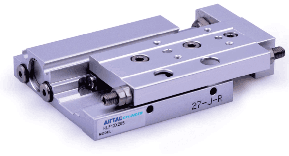
| Bauform / Code | Doppeltwirkender Zylinder mit integrierter Kreuzrollenführung, Bohrungen 8/12/16/20. Die Bestelltabelle nennt nur S mit Magnet; Anschlagdämpfung und metrische Anschlüsse, kein A/G/T-Suffix. Im Auswahlbeispiel HLF20X50 fehlt S; daraus ergibt sich keine bestellbare Ausführung ohne Magnet. |
| Standardhübe | 8: 10/20/30 mm; 12: 10/20/30/40/50; 16/20: 10/20/30/40/50/75/100. Maximum stroke is not every intermediate integer; non-standard strokes need consultation. |
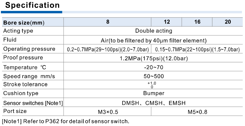
| Druck / Prüfdruck | 8: Betriebsdruck 0.2–0.7 MPa; 12/16/20: 0.15–0.7 MPa. Der Prüfdruck 1.2 MPa ist kein Betriebsdruck. Die Krafttabelle enthält 0.1 MPa unterhalb der Betriebsuntergrenze; daraus ergibt sich keine Betriebsfreigabe. |
| Luft / Geschwindigkeit / Toleranz | 40 μm filtered air, −20 to 70°C, 50–500 mm/s. Stroke tolerance +1.0/0 mm. Use low-temperature anti-freezing measures and keep dirt out of piping; storage ports capped and exposed parts protected against rust. |
| Anschlüsse / Sensoren | 8 M3×0.5; 12/16/20 M5×0.8. Side and end inlet/outlet pairs, top/bottom cylinder installation, top/side workpiece fastening. DMSH/CMSH/EMSH sensors need exact mounting/scope confirmation; source refers details to P362. |
| Theoretische Zylinderkraft | At 0.5 MPa bores 8/12/16/20 push 25.1/56.5/100.5/157 N; pull 21.6/50.3/86.4/131.9 N. Cylinder thrust N is separate from guide load kg, moment N·m and energy J. |
| Energie / Montage | Maximum bumper energy reference Emax for 8/12/16/20: 0.027/0.055/0.11/0.16 J. Mounting coefficient K=1 for slide-table workpiece mounting, K=0.6 for end-plate mounting. Allowable energy Ea=K×Emax. Source selection uses impact V=1.4×average Va; velocity in E uses m/s, not unconverted mm/s. |
| Last / Geschwindigkeit | Bezugswert Wmax für 8/12/16/20: 0.6/1/2/4 kg, keine allgemein zulässige Nutzlast. Zulässige Last Wa=K×β×Wmax mit dem Geschwindigkeitsbeiwert aus dem Diagramm. Bei vertikalem Einsatz entfällt laut Katalog der Anteil α1 für konzentrierte Last; Energie- und Momentprüfung bleiben erforderlich und begrenzen die Last für die konkrete Anwendung. |
| Veröffentlichte Momentzeilen | Mmax N·m: HLF8 strokes 10/20/30=0.56/0.78/0.98; HLF12 20/30/50=1.65/2.22/3.34; HLF16 30/50/70=3.41/5.69/7.96; HLF20 30/50/70/100=6.66/9.14/13.70/18.27. Moment table column says 70 while standard stroke table says 75. Do not transfer 70 values to 75; standard 75 moment remains unconfirmed. Other blank cells are not interpolated. |
| Statisch / Aufprall / Summe | Use pitch/yaw/roll mounting geometry and overhang L1/L2/L3. Static allowable Ma=K×γ×Mmax uses average speed Va, dynamic allowable Mea uses impact speed V. Source dynamic example uses bumper δ=4/100 and impact equivalent mass We=δ×W×V. Sum concentrated, static and dynamic load rates ≤1 after selecting the applicable components. |
| Korrekturabstände | A1..A6 mm: HLF8 [6,10,6,21,21,10], except stroke 10 A1/A3=16; HLF12 [10,11,10,23,23,11]; HLF16 [10,12,10,28,28,12]; HLF20 [11,17,11,34,34,17]. These are model-specific geometry corrections, not interchangeable offsets. |
| Hubeinstellung / Werkstoff | Extension/retraction end adjustment appears in bore-specific drawings: 8 extension 4.5 mm/retraction 5 mm; 12 6.5/6.5; 16 5.5/5.5; 20 7.5/7.5. Confirm assembled endpoint geometry, not an extra ordering suffix. Material illustration is based on a certain bore, not a universal BOM. |