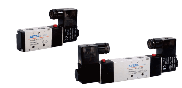
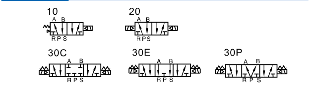
| Valve function and center | 10: single-solenoid 5/2; 20: double-solenoid 5/2 with memory; 30C: double-solenoid 5/3 closed center; 30E: exhaust center; 30P: pressure center. Match the circuit and desired center behavior. A memory or center choice is not a certified safety stop or load-holding guarantee. |
| Pilot and pressure | Internal or external pilot is stated in the specification. The published ordering table does not encode a pilot selector: confirm actual pilot arrangement, available pressure and circuit separately. Operating pressure 0.15–0.8 MPa; proof pressure 1.2 MPa is not an operating rating. |
| Air and temperature | Air filtered to 40 μm or finer; −20 to 70°C; aluminum alloy body. Lubrication not required. If lubrication is used, continue with the same medium; ISO VG32 or equivalent is recommended. |
| Voltage and electrical entry | A: AC220V; B: DC24V; C: AC110V; E: AC24V; F: DC12V. AC-Toleranz ±15%; DC ±10%. Leer: Klemmenanschluss; I: Kabelausgang mit 0.5 m Leitung. AC/DC, Spannung, Spulenleistung, Steckerausrichtung und Anschlussfreiräume bestätigen. |
| Coil and timing conditions | Insulation class B and IP65 (DIN40050) are published coil specifications; verify the complete installed connector/sealing arrangement. Activation time 0.05 s or below is not a complete machine-cycle guarantee. Maximum frequency 5 cycles/s for 10/20, 3 cycles/s for 30C/E/P, under no-load conditions. |
| Thread and code boundary | For inch ports, blank means PT, G means G thread, T means NPT. Center codes 30C/30E must not be confused with voltage codes C/E. Standard valve lookup does not establish explosion-proof, alternate-pilot, coil-only or manifold accessory compatibility. |
| Manifold and RFQ inputs | A manifold/base is a separate accessory, not a valve function. Confirm base model, station count, valve size, thread, blank plates and assembly from labels/drawings. Send valve and coil codes or photos, circuit, pressure/flow need, voltage/entry, ports, mounting envelope, quantity and destination for quotation. |
| 4V200 ports | 06: inlet, outlet and exhaust all 1/8. 08: inlet/outlet 1/4, exhaust remains 1/8. Match PT/G/NPT thread and actual exhaust routing; 08 does not mean all five ports are 1/4. |
| 4V200 coil power and weight | AC220/110: 4.5VA; AC24: 5.0VA; DC24: 3.0W; DC12: 2.5W. Valve weights: 220g single 5/2, 320g double 5/2, 360g three-position. |
| 4V200 published flow scope | 4V210-08 and 4V220-08: equivalent area 17 mm², Cv 1.0; 4V230C-08: 13.6 mm², Cv 0.8. This row does not individually rate 06 or 30E/30P; confirm those separately. Flow chart specifically illustrates 4V210-08 under AirTAC laboratory conditions, not an unconditional L/min promise. |
| 4V200 mounting and base reference | Zeichnungen für 4V210, 4V220 und 4V230 mit Klemmenanschluss/Kabelausgang und deren 06/08-Maßtabellen verwenden. Abluft A ist bei beiden 1/8; Arbeitsanschluss B ist 1/8 oder 1/4. Der Bestellhinweis verweist auf die gedruckte Ventilinselseite 96, die in dieser zweiseitigen Ventil-PDF fehlt; maßgeblich ist das separate offizielle Ventilinselblatt, nicht Ventilseite 88. |