AirTAC SED ISO15552 Zylinder
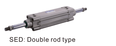
Code, Bohrung,Hub,Montage,Menge und Lieferziel senden. SE/SED/SEJ Ausführung und Einbau...
Offizielle Referenz
Nach Herstellerunterlagen
Modellhilfe
Für die Modellprüfung
Teilelisten
Code, Foto oder BOM
Verfügbarkeit / Lieferzeit
Nach Modell und Menge
Beschaffungsweg & Anfragehinweise
Code, Bohrung,Hub,Montage,Menge und Lieferziel senden. SE/SED/SEJ Ausführung und Einbau bestätigen.
Modell bekannt? Für ein Angebot direkt Modell und Menge senden. Modell unklar? Mit Foto, Etikett oder Beschreibung starten. Wir helfen bei der Identifikation und klären Verfügbarkeit und Lieferzeit. Auch gemischte Teilelisten sind willkommen.
SE/BSE-Modell abgleichen
Teil der SE-Serienfamilie.
Familienübersicht ansehen →Zeichnung, Maße & technische Kenndaten
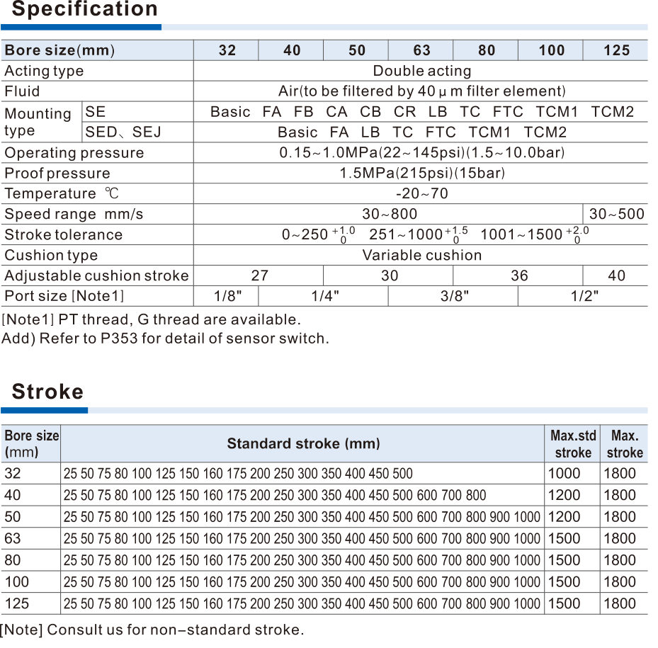
AirTAC SED official se specification strokes
Hilfreich für den Modellabgleich:
- Code,Typenschild oder Zeichnung
- Bohrung,Hub,SEJ Verstellung
- Magnet,Montage,Gewinde
- SE Werkstoff oder BSE Freigabe
- Last,Geschwindigkeit,Umgebung,Steuerung
- Menge, Lieferziel
- Confirm actualfamily/function,installed length and mount
- Check bore,stroke,adjustment,rod/thread and magnet
- ForBSE verify static load,pressure balance and release timing
- Confirm construction-specific accessory compatibility
Technische Katalogdaten
| Construction / standards | SE-Standardzylinder mit Aluminiumprofil ohne Zugstangen; ISO15552/VDMA24562. SED mit Doppelstange; SEJ mit Doppelstange und verstellbarem Hub. Alle doppeltwirkend. Bohrungen 32/40/50/63/80/100/125 mm. ISO-Konformität allein gewährleistet keinen direkten Austausch ohne Anpassung. |
| Operating conditions | Filtered air40μm or finer;operating pressure0.15–1.0MPa;proof1.5MPa is not continuous service pressure. Standard temperature−20to70°C. Speed30–800mm/s for32–100;125 bore30–500mm/s. Adjustable pneumatic cushion at both ends;side loading and contamination require application review. |
| Published strokes | 32:25/50/75/80/100/125/150/160/175/200/250/300/350/400/450/500;40 adds600/700/800;50–125 add600/700/800/900/1000. These are standard code-matching strokes,not all buildable strokes. English max standard32=1000,40/50=1200,63–125=1500;newerChinese32/40=1000,50–125=1500. Both give maximum1800 by consultation. This source-version conflict and nonlisted strokes require confirmation;only standard strokes listed in both catalogues can be matched directly. |
| SE ordering | SE/SED/SEJ[bore][rod]×[stroke][-adjustment][S][mount][seal][G]. Blank rod medium carbon steel;A SUS420J2;B SUS304;English source alsoC SUS316,absent in newerChinese matrix,confirm source/version forC. Blank no magnet;S magnet. Blank sealTPU;H Viton;N NBR. BlankPT/G G-thread;noNPT code. |
| SEJ adjustment | SEJ alone requires10/20/30/40/50/75/100mm adjustment field following main stroke;it is double-rod adjustable travel,not a single-rod cylinder with arbitrary negative stroke. Both main and adjustment lengths affect installed envelope. |
| Ports / rod interface | Bore32 port1/8;40/50 port1/4;63/80 port3/8;100/125 port1/2. Rod threads32 M10×1.25;40 M12×1.25;50/63 M16×1.5;80 M20×1.5;100 M20×1.5;125 M27×2. Match end-face holes,mounting centres,port orientation and total-length formula. |
| Mounting / accessories | SE ohne Zusatz/LB/FA/FB/CA/CB/CR/FTC/TC; SED/SEJ ohne Zusatz/LB/FA/FTC/TC. CR erfordert CB und ist nicht allein verwendbar. FTC/TC werden mit TCM1/TCM2 eingesetzt; die Einbaulage ist nicht frei verstellbar. Die offizielle Zuordnungstabelle enthält Zubehör mit F-SI- und F-SE-Präfix. Entscheidend ist der genaue Tabelleneintrag, nicht allein das Präfix. |
| Sensors / magnet | Three sensor grooves;CMSE/DMSE named in this source. Sensor use requires S magnet;do not imply standard blank magnet or included sensor. Magnet and nonmagnet external dimensions same as table;thread and mount still need confirmation. |
| Forces / cushion | Theoretical thrust table inN,depends on actual pressure and push/pull area;not guaranteed usable load. Rod diameter32/40/50/63/80/100/125:12/16/20/20/25/25/32mm. Cushion stroke27mm for32/40;30 for50/63;36 for80/100;40 for125. |
| TC clamp force versus locking | TC bracket static clamp table800/1200/2000/3000/5000/8000/12000N and torque2–3/4–6/4–6/7–12/12–20/12–20/18–30N·m by bore. This is mounting-bracket clamp force,not BSE rod holding force or cylinder output. Never use it as BSE brake rating. |
Sonderhub oder unvollständiger Code? Foto oder BOM einreichen.
Modellcode, Kompatibilität & Spezifikationen
Bestellcode-Abgleich
Code Schritt für Schritt vergleichen
Unterstütztes Codemuster
SE/SED/SEJ [bore][rod]×[stroke][-adjustment][S][mount][seal][G]Ausführungsspezifische Optionen undSonderhub bestätigenSED80BX100SLBHG| 1Family / function | 2Bore / stroke | 3Material / adjustment | 4Magnet / mount | 5Threads / lock release |
|---|---|---|---|---|
| SE baseline;SED double rod;SEJ double rod adjustable;BSE/BSED static-locking independent family. | 32/40/50/63/80/100/125;only published standard combinations auto-matched. | SE rod A/B/C English-only C,seals H/N;SEJ adjustment mandatory;BSE has neither rod nor seal optionalfield. | Blank no magnet/S;mounting options vary by construction. | Cylinder blankPT/G;BSE separate releaseG1/8;noNPT. |
Fragen zum Abgleich
Kann BSE eine bewegte Last abbremsen und passt SE direkt?
BSE nur statisch nachStillstand verriegeln;Druck vor Freigabe ausgleichen. Keine dynamische Bremse. Ausführung,Zeichnung,Last und Steuerung separat bestätigen.
SED
Diese Serie zum Projektangebot hinzufügen
SED zusammen mit weiteren Modellen, Mengen, Fotos, Zeichnungen oder einer BOM-Liste senden. Eine Anfrage kann mehrere Produktgruppen abdecken.
Passende Systemkomponenten
Ergänzen Sie Ihre Pneumatik mit passenden Komponenten. Maße und Betriebsbedingungen vor der Auswahl einer Kombination prüfen.
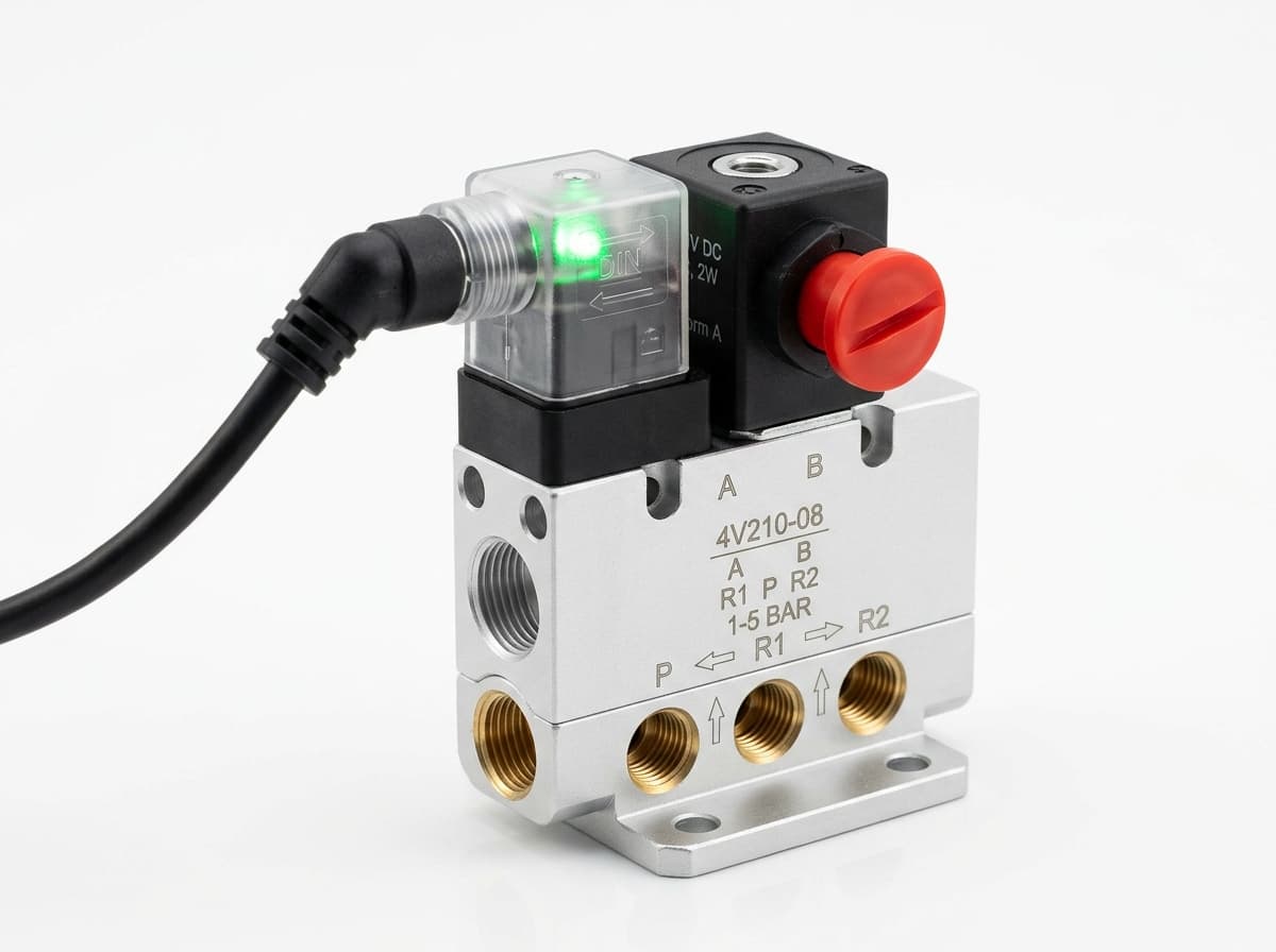
Produktgruppen-Referenzbild
Wegeventile
Pneumatik schalten. Ventilfunktion, Durchfluss, Anschlussgröße und Ansteuerung passend zur Anwendung wählen.
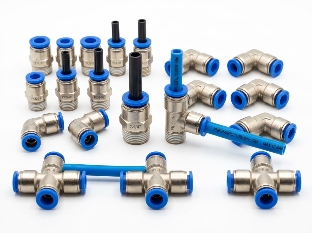
Produktgruppen-Referenzbild
PneuPart SL Drosselrückschlagventile
Luftstrom am Antrieb einstellen. Gewinde, Schlauchmaß, Durchflussrichtung und Durchflussbedarf prüfen.
Produktgruppen-Referenzbild
PneuPart Schlauchverbinder
Schlauch mit Ventil oder Antrieb verbinden. Außenmaß, Anschlussgewinde und Dichtung abgleichen.
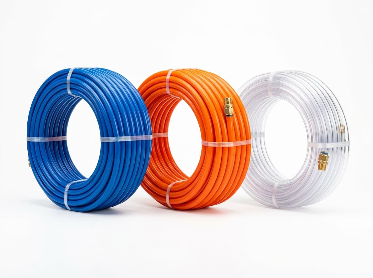
Produktgruppen-Referenzbild
PneuPart Pneumatikschläuche
Luftleitungen zwischen Verbindern und Komponenten verlegen. Außenmaß, Biegeradius, Druck und Temperatur prüfen.
Komplette Baugruppe oder Misch-BOM anfragen?
Senden Sie Ihre Teileliste, Anschlussmaße und Betriebsbedingungen zur gemeinsamen Prüfung und Angebotserstellung.