AirTAC SAIF Zylinder mit integriertem Magnetventil
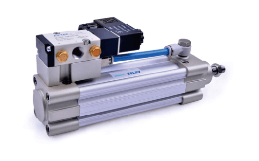
Zylinder mit integriertem Magnetventil. Modellcode, Zeichnung, Menge und Lieferziel für ein...
Offizielle Referenz
Nach Herstellerunterlagen
Modellhilfe
Für die Modellprüfung
Teilelisten
Code, Foto oder BOM
Verfügbarkeit / Lieferzeit
Nach Modell und Menge
Beschaffungsweg & Anfragehinweise
Zylinder mit integriertem Magnetventil. Modellcode, Zeichnung, Menge und Lieferziel für ein Angebot senden.
Modell bekannt? Für ein Angebot direkt Modell und Menge senden. Modell unklar? Mit Foto, Etikett oder Beschreibung starten. Wir helfen bei der Identifikation und klären Verfügbarkeit und Lieferzeit. Auch gemischte Teilelisten sind willkommen.
SAI-Modell abgleichen
Teil der SAI-Serienfamilie.
Familienübersicht ansehen →Zeichnung, Maße & technische Kenndaten
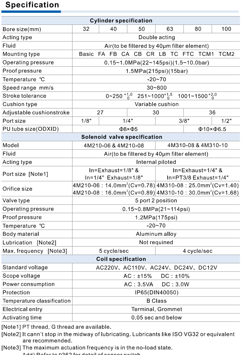
AirTAC SAIF official saif specifications
Hilfreich für den Modellabgleich:
- Modellcode oder Etikett
- Durchmesser, Hub und Hubeinstellung
- Montage- und Anschlusszeichnung
- Magnet, Dichtung und Temperatur
- Verriegelung oder Ventilspannung/Anschluss/Funktion
- Menge und Lieferziel
- Confirm functional derivative and its own dimensions
- Confirm working stroke, adjustment and mounting
- Separate rod end, cylinder port and valve port
- Check lock/valve and large-bore trunnion conditions
Technische Katalogdaten
| Cylinder pressure / proof | Operating 0.15–1.0 MPa; proof 1.5 MPa. Proof is not continuous operating pressure. |
| Medium / temperature | Mit 40 μm gefilterte Luft; −20–70°C; doppeltwirkend; einstellbare pneumatische Dämpfung. |
| Speed | 32–125: 30–800 mm/s; 160/200: 30–500 mm/s. Apply only to the current variant bore range. |
| Cylinder ports | 32: 1/8; 40/50: 1/4; 63/80: 3/8; 100/125: 1/2; 160/200: 3/4. Blank PT / optional G; no NPT field. |
| Rod end | 32: M10×1.25; 40: M12×1.25; 50/63: M16×1.5; 80/100: M20×1.5; 125: M27×2; 160/200: M36×2. Separate from air port. |
| Magnet / switch | Blank without magnet; S with magnet; CMSE / DMSE switches separately selected. Magnetic and non-magnetic dimensions are the same. |
| Mounting accessories | CR must be used with CB, not alone. FTC / TC use TCM1 / TCM2. TC 160/200 is factory installed on the barrel; position cannot be adjusted arbitrarily and cannot be assumed to retrofit a cylinder ordered without TC. TCM1/2 positions for 160/200 cannot be adjusted arbitrarily. |
| Fit / force | ISO15552, originally ISO6431. Confirm installed dimensions, rod-end, load, side loads and cushion. ISO alone does not guarantee interchangeability. Thrust is N at specified pressure, not payload kg. |
| Stroke tolerance | 0–250: +1/0; 251–1000: +1.5/0; 1001–1500: +2/0 mm. No extrapolation above 1500 mm. |
| Bore / strokes | 32/40/50/63/80/100 only. Minimum stroke 50 mm; TC minimum 125 mm. Enumerated strokes follow SAI but start at 50 mm. Maximum standard 32: 1000; 40/50: 1200; 63/80/100: 1500 mm; maximum stroke 1800 mm. Unlisted strokes require confirmation. |
| Assembly pressure | Cylinder 0.15–1.0 MPa / proof 1.5 MPa; valve 0.15–0.8 MPa / proof 1.2 MPa. Complete assembly must satisfy both; cylinder 1.0 MPa is not valve operating rating. |
| Valve / ports | Internal-pilot 5-port 2-position. 32/40/50: 4M210-06 or -08; 63/80/100: 4M310-08 or -10. 06=1/8, 08=1/4, 10=3/8. Valve port differs from cylinder port. |
| Voltage / entry | A AC220V; B DC24V; C AC110V; E AC24V; F DC12V. Leer Klemmenanschluss / I Kabelausgang. Kein D-Feld. AC ±15%, DC ±10%; AC 3.5 VA, DC 3 W; IP65 DIN40050, Klasse B. |
| Energized motion | Factory default rod retracts when energized; valve can be repositioned to extend with correct seals. Confirm required operation using SAIF drawing; no extra polarity suffix published. |
| Valve speed / tubing | 4M210: 5 cycles/s; 4M310: 4 cycles/s, no-load condition. PU tube 32/40/50 OD8×ID5; 63/80/100 OD10×ID6.5 mm. Valve and cylinder −20–70°C. |
| Mounting / omitted fields | Blank/LB/FA/FB/CA/CB/CR/FTC/TC; optional S magnet and G thread. No SAI rod A/B or seal H/N fields. Valve port and voltage mandatory. |
Sonderhub oder unvollständiger Code? Foto oder BOM einreichen.
Modellcode, Kompatibilität & Spezifikationen
Bestellcode-Abgleich
Code Schritt für Schritt vergleichen
Unterstütztes Codemuster
SAIF50X100S-06BNur veröffentlichte Felder dieser Variante abgleichenSAIF50X100S-06BSAIF80X200STC-10AIG| 1Model | 2Bore / main stroke | 3Magnet | 4Mounting | 5Valve port | 6Voltage | 7Electrical entry | 8Thread |
|---|---|---|---|---|---|---|---|
| SAIF functional construction | Aufgeführte Kombinationen aus Bohrung und Hub verwenden; nicht aufgeführte Hübe erfordern Bestätigung. | Blank without magnet; S with magnet. | Blank / LB / FA / FB / CA / CB / CR / FTC / TC. | After hyphen: 06/08 for bore32/40/50; 08/10 for bore63/80/100. | A AC220V; B DC24V; C AC110V; E AC24V; F DC12V. | Leer Klemmenanschluss; I Kabelausgang. | Blank PT; G optional. No NPT field. |
Fragen zum Abgleich
Welche Funktion und Schnittstellen sind zu bestätigen?
Zylinder mit integriertem Magnetventil. Vollständigen Code und variantenspezifische Zeichnung mit Menge und Lieferziel senden; ISO allein garantiert keine Austauschbarkeit.
SAIF
Diese Serie zum Projektangebot hinzufügen
SAIF zusammen mit weiteren Modellen, Mengen, Fotos, Zeichnungen oder einer BOM-Liste senden. Eine Anfrage kann mehrere Produktgruppen abdecken.
Passende Systemkomponenten
Ergänzen Sie Ihre Pneumatik mit passenden Komponenten. Maße und Betriebsbedingungen vor der Auswahl einer Kombination prüfen.
Produktgruppen-Referenzbild
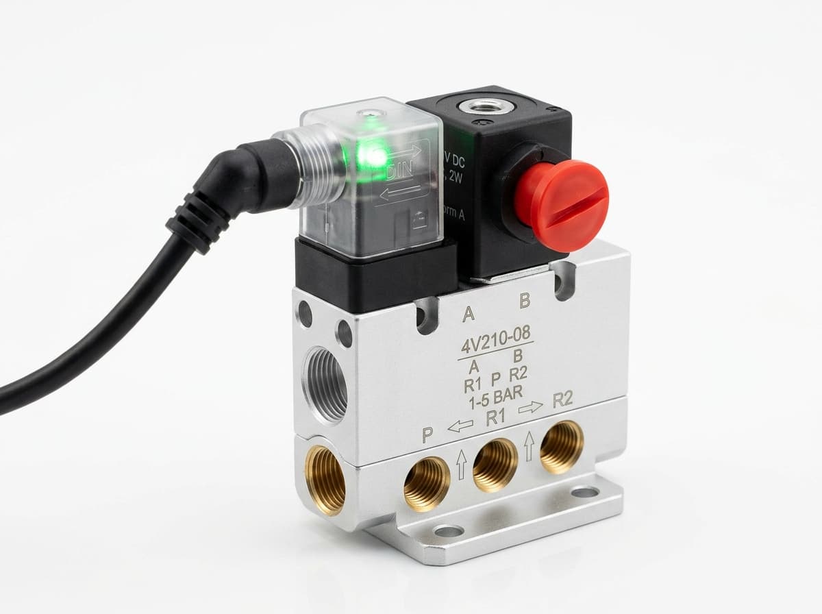
Wegeventile
Pneumatik schalten. Ventilfunktion, Durchfluss, Anschlussgröße und Ansteuerung passend zur Anwendung wählen.
Produktgruppen-Referenzbild
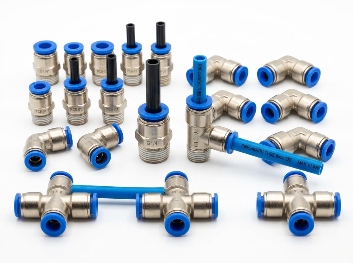
PneuPart SL Drosselrückschlagventile
Luftstrom am Antrieb einstellen. Gewinde, Schlauchmaß, Durchflussrichtung und Durchflussbedarf prüfen.
Produktgruppen-Referenzbild
PneuPart Schlauchverbinder
Schlauch mit Ventil oder Antrieb verbinden. Außenmaß, Anschlussgewinde und Dichtung abgleichen.
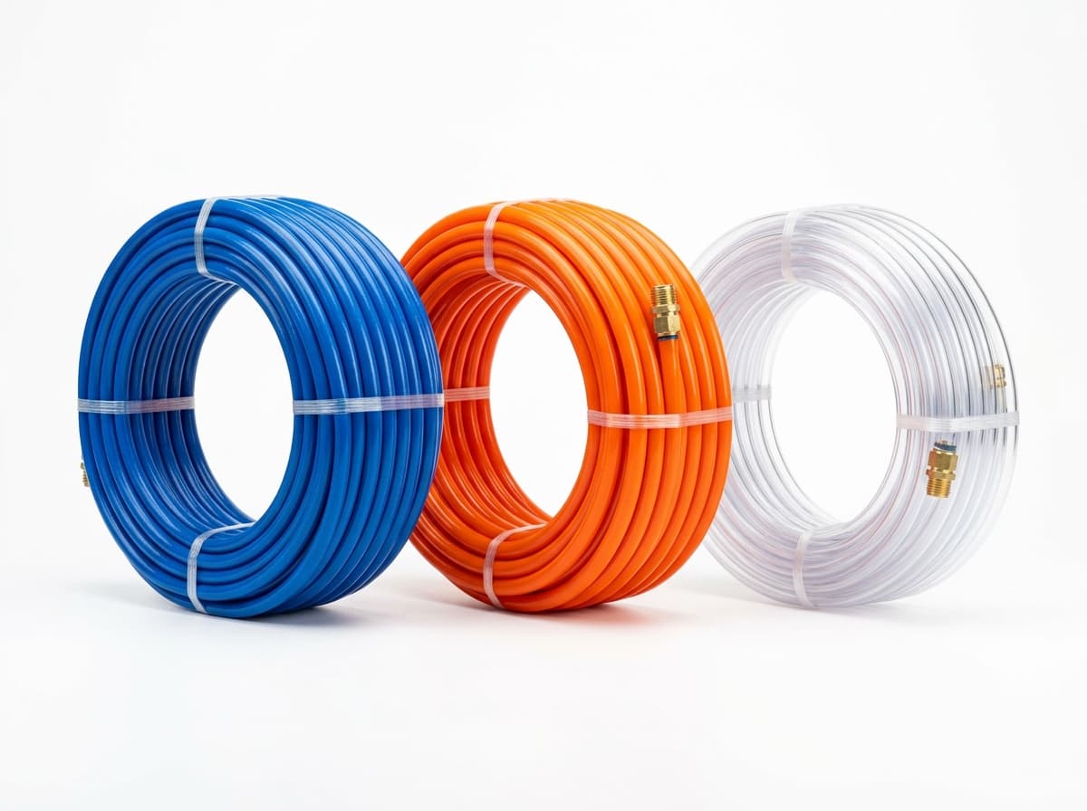
Produktgruppen-Referenzbild
PneuPart Pneumatikschläuche
Luftleitungen zwischen Verbindern und Komponenten verlegen. Außenmaß, Biegeradius, Druck und Temperatur prüfen.
Komplette Baugruppe oder Misch-BOM anfragen?
Senden Sie Ihre Teileliste, Anschlussmaße und Betriebsbedingungen zur gemeinsamen Prüfung und Angebotserstellung.