Find your TMIC type
Choose a type; send a model or photo if unsure.
TMI
TMI12 bumper guided cylinder
TMIC
TMIC16/20/25 adjustable-cushion guided cylinder
Send the model, quantity and destination. For multiple items, attach a parts list or BOM.

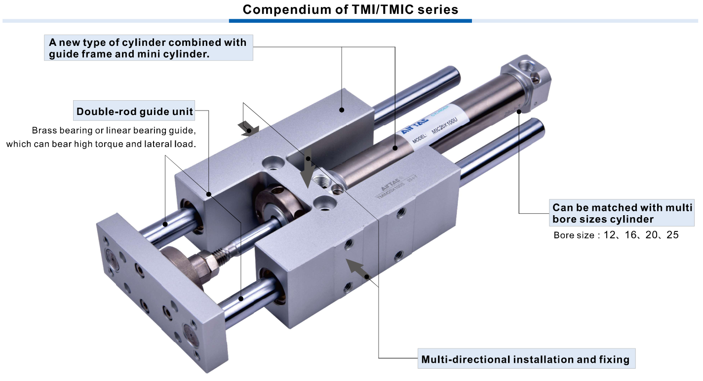
AirTAC TMI12 and TMIC16/20/25 double-acting guided mini cylinders, M brass or L linear...
Official reference
Based on manufacturer documentation
Model support
For model confirmation
Parts lists
Code, photo, or BOM
Availability / lead time
By model and quantity
AirTAC TMI12 and TMIC16/20/25 double-acting guided mini cylinders, M brass or L linear bearings, with separately ordered F guide frames. Match cushion, standard stroke, rear-cover/ports and load/overhang before quotation.
Know your model? Send it with the quantity for a quote. Not sure? Start with a photo, label or description. We help identify the model and clarify availability and lead time. Mixed parts lists are welcome too.
Choose a type; send a model or photo if unsure.
TMI
TMI12 bumper guided cylinder
TMIC
TMIC16/20/25 adjustable-cushion guided cylinder
Send the model, quantity and destination. For multiple items, attach a parts list or BOM.
AirTAC TMI TMIC overview product official English reference
Helpful for Model Matching:
| Identity and bearing | TMI/TMIC combines the matching MI/MIC mini cylinder and a double-rod guide frame. M is brass bearing, not steel-ball guide; L is linear bearing. All published assemblies double acting. Guide load behavior and interfaces are separate from the ordinary MI/MIC cylinder alone. |
| Model and cushion | Ordering table partitions TMI12 bumper version and TMIC16/20/25 adjustable-cushion versions. Do not recognize TMIC12 or TMI16/20/25 as standard from this sheet. Matching cylinder uses perpendicular90° rear cover; confirm actual connector/port orientation. |
| Strokes | 12/16 standard25/50/75/100/125/150/200 mm, max200;20/25 also250 mm, max250. Nonstandard strokes require confirmation. Separate frames are ordered at standard strokes; nonstandard cylinder combines with the next upper standard frame, subject to drawing and supply confirmation. |
| Conditions | Operating0.15–1.0 MPa, proof1.5 MPa separate; filtered air40 μm; −20 to70°C; speed30–500 mm/s. Stroke tolerance≤150 mm +1.0/0; >150 mm +1.5/0. No universal guide load capacity follows from pressure or bore. |
| Ports and mounting | 12/16 M5×0.8;20/25 PT1/8 blank or G1/8 G. No NPT field. Own guide-frame drawings show multi-direction fixing: mounting threads M5×0.8 for12/16, M6×1.0 for20/25. Full plate/hole patterns and rear-cover clearance must be matched to own drawing. |
| Magnet and supply | Blank no magnet, S magnet for complete cylinder; sensor model and inclusion separately confirmed. F-TMI/ F-TMIC denotes guide-frame accessory only, without cylinder magnetic/thread selectors. The guide frame is supplied as an accessory; confirm the cylinder separately for a complete assembly. |
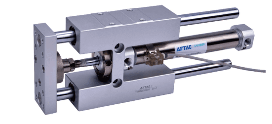
| Load and overhang | Separate maximum-load curves label M brass bearing and L linear bearing, each by bore and S overhang in mm against F N. M generally has higher allowable radial force in the published curves; L lower friction/high push-up accuracy. No one fixed kg/N/torque rating or application fit is guaranteed. Send force direction, load, overhang, stroke and cycle. |
| Nonstandard combination | Source example MIC20X160 cylinder + F-TMICM20X200 standard frame has AC+200 guide-frame envelope but A+160 cylinder envelope. Do not resolve the combined text as one standard160-stroke assembled code; keep original request for engineering confirmation. |
| RFQ inputs | Send complete TMI/TMIC or F-frame code, M/L bearing, bore/stroke, magnet/sensor, rear-cover and port photos, own mounting drawing, load/overhang/cycle, exact cylinder+frame supply scope, quantity and destination. |
Ordering code matching
Code format
[TMI12 / TMIC16,20,25] with [M/L][bore]X[standard stroke][S][G where applicable]F prefix is frame only; no magnet/thread field on frame.TMIM12X100STMICM20X100SGTMICL16X200F-TMICL25X250| 1Model and guide | 2Stroke | 3Magnet and thread |
|---|---|---|
| TMI/TMIC combines the matching MI/MIC mini cylinder and a double-rod guide frame. M is brass bearing, not steel-ball guide; L is linear bearing. All published assemblies double acting. Guide load behavior and interfaces are separate from the ordinary MI/MIC cylinder alone. Ordering table partitions TMI12 bumper version and TMIC16/20/25 adjustable-cushion versions. Do not recognize TMIC12 or TMI16/20/25 as standard from this sheet. Matching cylinder uses perpendicular90° rear cover; confirm actual connector/port orientation. | 12/16 standard25/50/75/100/125/150/200 mm, max200;20/25 also250 mm, max250. Nonstandard strokes require confirmation. Separate frames are ordered at standard strokes; nonstandard cylinder combines with the next upper standard frame, subject to drawing and supply confirmation. | 12/16 M5×0.8;20/25 PT1/8 blank or G1/8 G. No NPT field. Own guide-frame drawings show multi-direction fixing: mounting threads M5×0.8 for12/16, M6×1.0 for20/25. Full plate/hole patterns and rear-cover clearance must be matched to own drawing. Blank no magnet, S magnet for complete cylinder; sensor model and inclusion separately confirmed. F-TMI/ F-TMIC denotes guide-frame accessory only, without cylinder magnetic/thread selectors. The guide frame is supplied as an accessory; confirm the cylinder separately for a complete assembly. |
If the label is incomplete, send the readable parts together with a photo.
TMICM20X100SG1Model and guide
TMI/TMIC combines the matching MI/MIC mini cylinder and a double-rod guide frame. M is brass bearing, not steel-ball guide; L is linear bearing. All published assemblies double acting. Guide load behavior and interfaces are separate from the ordinary MI/MIC cylinder alone. Ordering table partitions TMI12 bumper version and TMIC16/20/25 adjustable-cushion versions. Do not recognize TMIC12 or TMI16/20/25 as standard from this sheet. Matching cylinder uses perpendicular90° rear cover; confirm actual connector/port orientation.
2Stroke
12/16 standard25/50/75/100/125/150/200 mm, max200;20/25 also250 mm, max250. Nonstandard strokes require confirmation. Separate frames are ordered at standard strokes; nonstandard cylinder combines with the next upper standard frame, subject to drawing and supply confirmation.
3Magnet and thread
12/16 M5×0.8;20/25 PT1/8 blank or G1/8 G. No NPT field. Own guide-frame drawings show multi-direction fixing: mounting threads M5×0.8 for12/16, M6×1.0 for20/25. Full plate/hole patterns and rear-cover clearance must be matched to own drawing. Blank no magnet, S magnet for complete cylinder; sensor model and inclusion separately confirmed. F-TMI/ F-TMIC denotes guide-frame accessory only, without cylinder magnetic/thread selectors. The guide frame is supplied as an accessory; confirm the cylinder separately for a complete assembly.
AirTAC TMI12 and TMIC16/20/25 double-acting guided mini cylinders, M brass or L linear bearings, with separately ordered F guide frames. Match cushion, standard stroke, rear-cover/ports and load/overhang before quotation.
No. M denotes brass bearing; L linear bearing. F-TMIC is separately supplied guide-frame accessory, not a complete cylinder. Confirm cylinder, standard frame stroke, rear cover, ports, bearing load curve and actual mounting before quotation.
TMIC
TMIC Add other models, quantities, photos, drawings, or a BOM. One request can cover several product groups.
Build your pneumatic circuit with complementary components. Confirm dimensions and operating conditions before selecting a combination.

Product-group reference image
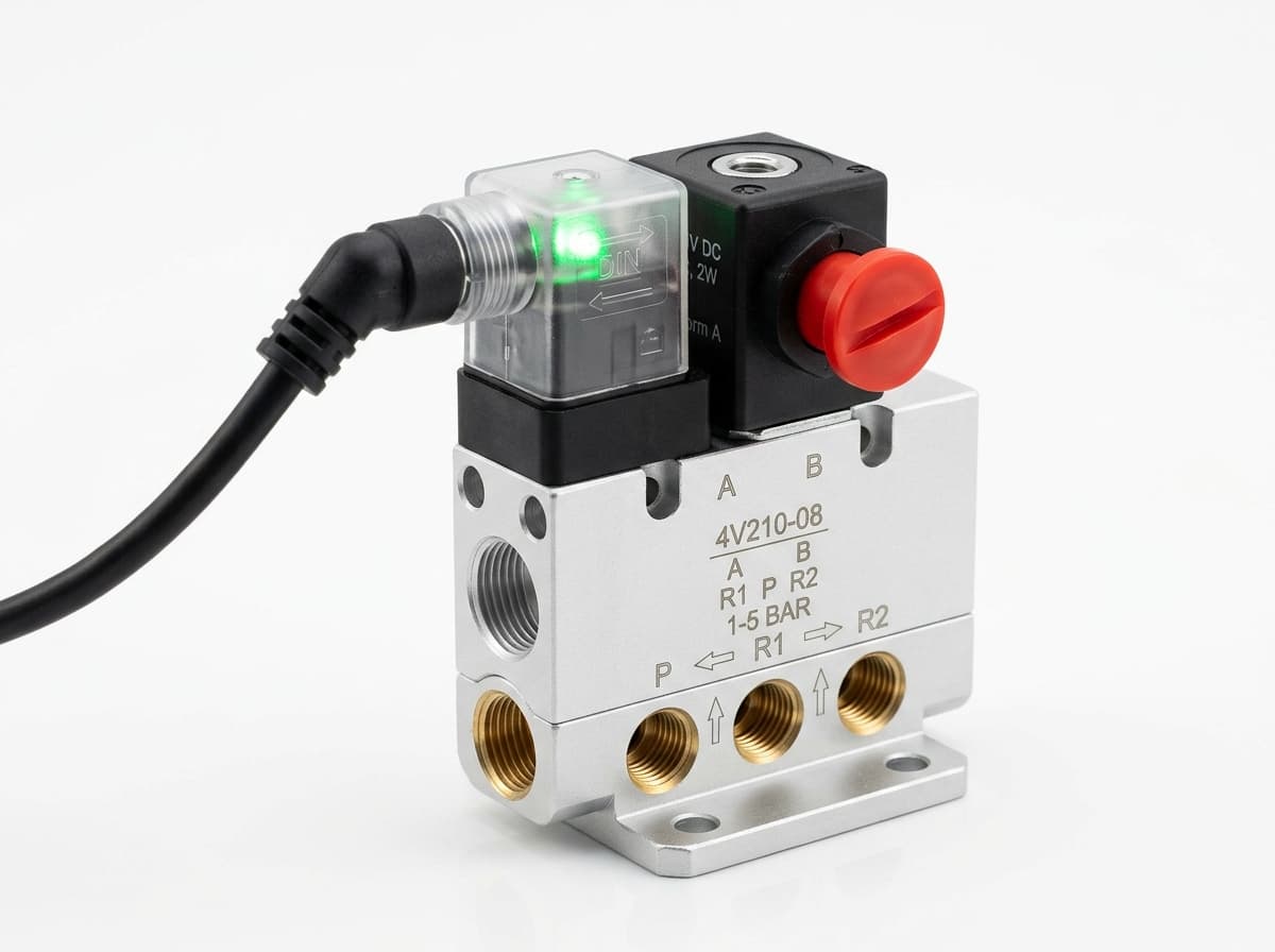
Switch the pneumatic circuit. Select the valve function, flow capacity, port size and control signal for the application.

Product-group reference image
Control actuator air flow. Confirm thread, tube size, flow direction and required flow rate.

Product-group reference image
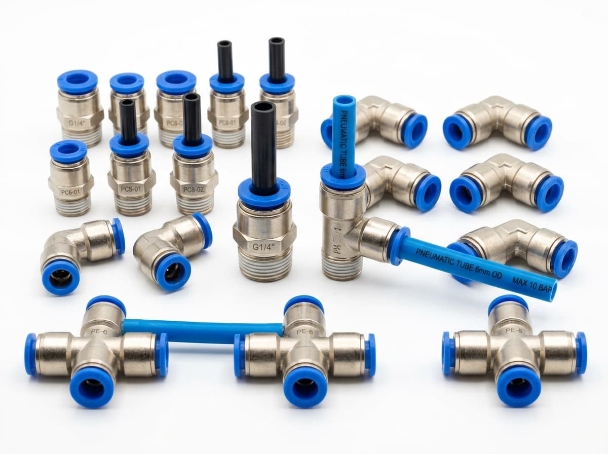
Connect tubing to a valve or actuator. Match tube outside diameter, port thread and seal type.

Product-group reference image
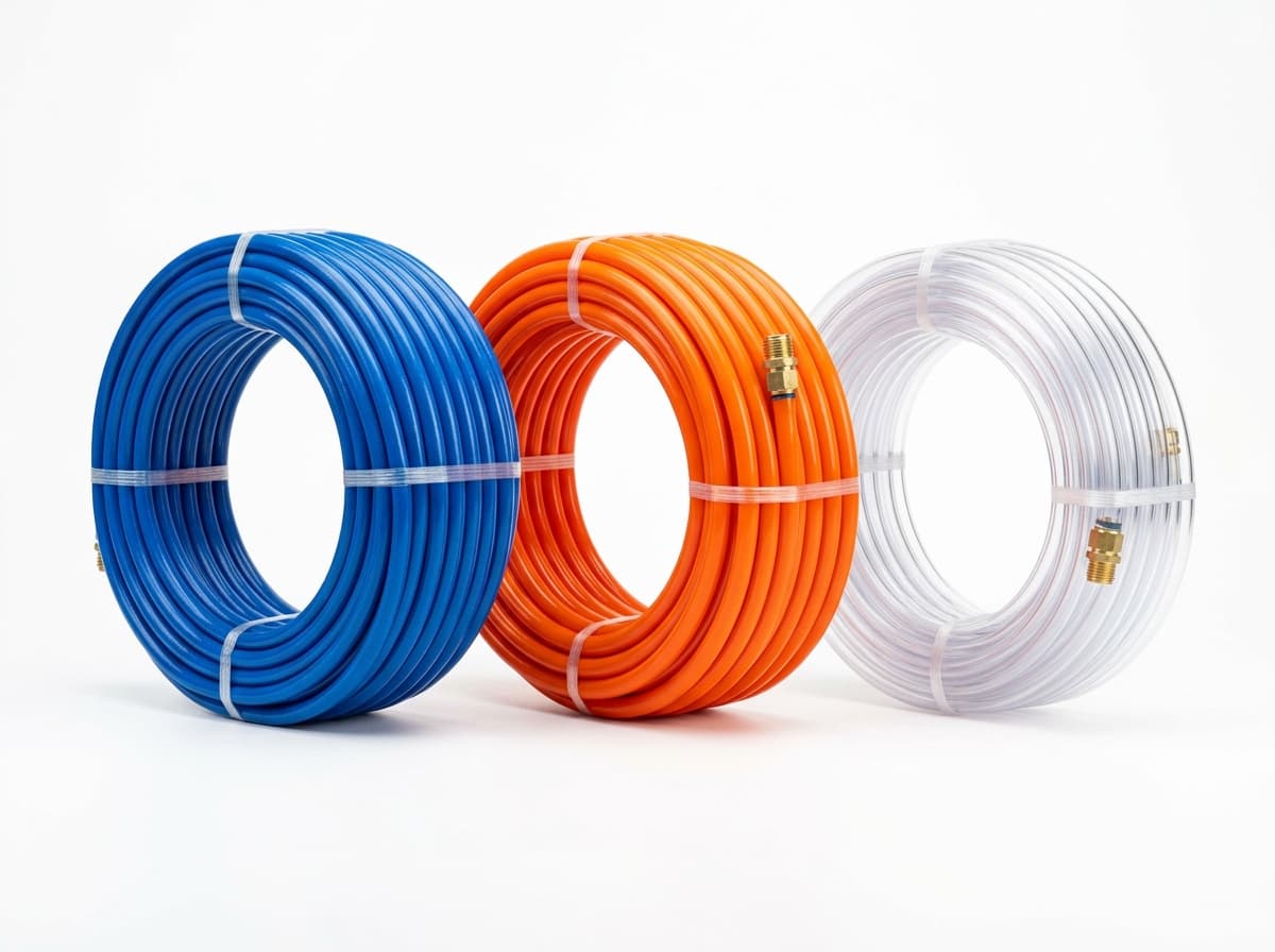
Run air lines between fittings and components. Confirm outside diameter, bend radius, pressure and temperature.
Send your parts list, connection sizes and operating conditions for a matching check and combined quotation.