AirTAC HFCQ-E Grippers with Pneumatic Push Rod
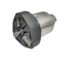
HFCQ32/40/50/63E combine a hollow three-finger gripper with a pneumatic push rod. Confirm the...
Official reference
Based on manufacturer documentation
Model support
For model confirmation
Parts lists
Code, photo, or BOM
Availability / lead time
By model and quantity
Sourcing route & inquiry details
HFCQ32/40/50/63E combine a hollow three-finger gripper with a pneumatic push rod. Confirm the gripper force and separate push stroke/pressure/force; send installed drawing, quantity and destination.
Know your model? Send it with the quantity for a quote. Not sure? Start with a photo, label or description. We help identify the model and clarify availability and lead time. Mixed parts lists are welcome too.
Match an HFCQ gripper model
Part of the HFCQ Series family.
View family overview →Installation Drawings & Technical Specifications
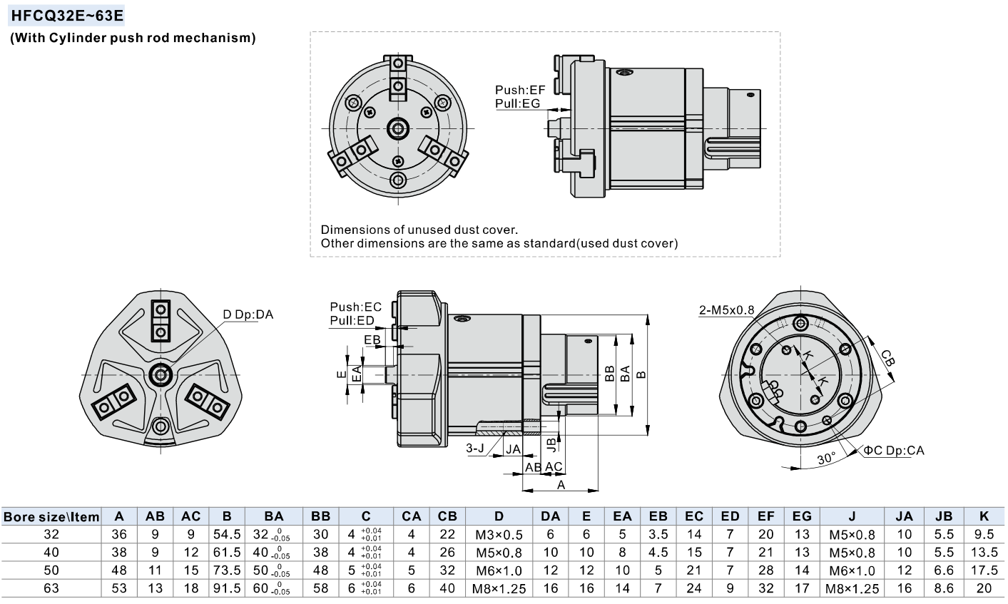
AirTAC HFCQ official e dimensions
Helpful for Model Matching:
- Full HFCQ code or label photo
- Base 16–63 or E/V32–63 push construction
- Internal/external grip, point L and jaw/workpiece drawing
- Workpiece mass, friction, pressure and motion acceleration
- Separate push stroke/force requirement and sensor requirement
- Quantity and destination
- Match base, E pneumatic or V spring construction
- Confirm per-finger force conditions and gripping point L
- Separate total jaw stroke from push stroke/force
- Check mounting depth/torque and jaw fitting screw torque
Catalogue Technical Specifications
| Construction / acting | Hollow three-finger parallel open/close; double acting gripper; magnet included; dust jacket; stainless steel jaws and piston rods |
| Base pressure / medium | 16/20:0.2–0.7 MPa; 25/32/40/50/63:0.15–0.7 MPa.40 μm filtered air; −20–70°C; no lubrication required |
| Repeatability / frequency | Repeatability ±0.01 mm; maximum gripper frequency 120 cycles/min for 16/20/25, 60 for 32/40/50/63 |
| Ports / hollow bore | Air port16:M3×0.5; 20/25/32/40/50/63:M5×0.8. Hollow diameters16/20/25/32/40/50/63=3/3/4/6/10/12/16 mm; match tolerance and interface on drawings |
| Gripping force per finger, internal/external | At0.5 MPa; L20 mm for 16/20/25 and L30 mm for 32/40/50/63.16=15/9; 20=26/21; 25=45/36; 32=77/62; 40=118/97; 50=187/155; 63=329/280 N. Not payload kg; force changes with L and pressure |
| Total jaw stroke, both sides | 16/20/25/32/40/50/63=4/4/6/8/8/12/16 mm. Separate from push stroke; this is not per-jaw travel |
| Push options / interface | E pneumatic or V spring push only 32/40/50/63. Push module pneumatic port M5×0.8; no suffix on base model for sensors or threads |
| Selection / workpiece | Check internal/external grip, gripping point L, workpiece mass, friction and acceleration/shock. Catalogue illustrates10–20×weight safety selection under its stated conditions; do not convert table force directly into guaranteed payload |
| Jaw fitting screw torque | 16/20/25:M3×0.5, 0.59 N·m; 32/40:M4×0.7, 1.4 N·m; 50/63:M5×0.8, 2.8 N·m. Hold jaw with spanner; do not clamp body to tighten jaw fittings |
| Mounting / pressure loss | Tail/front-through-hole mounting uses separate bolt/depth/torque tables, including push versions. Avoid impact and jaw twisting. Pressure loss reduces grip; provide anti-drop protection as needed for fixture |
| Pneumatic push pressure | 32E:0.2–0.7 MPa; 40E/50E/63E:0.15–0.7 MPa. Gripper32 base minimum0.15 does not override its E module minimum0.2 |
| Pneumatic push stroke / force | 32/40/50/63:push stroke 7/8/14/15 mm; push force 45/130/204/335 N at 0.5 MPa; 60 cycles/min maximum. Push force is separate from gripping force |
| Pneumatic push sensor | DMSH, CMSH, EMSH separately selected; show E-specific housing/ports and mounting drawing |
Ordering Codes, Fit Verification & Specifications
Ordering code matching
Match each code segment
Code format
HFCQ [32/40/50/63] ENo magnet, stroke or pipe-thread suffix publishedHFCQ32EHFCQ40EHFCQ63E| 1Bore | 2Push mechanism | 3Magnet / sensor | 4Port / stroke |
|---|---|---|---|
| Base 16/20/25/32/40/50/63. E/V push versions only 32/40/50/63. | Blank without push rod; E double-acting pneumatic push; V spring push. Separate module code F-HFCQ[bore]E/V. | All HFCQ have magnet; no S code field. CMSH/DMSH/EMSH sensors are separate. | 16:M3×0.5; other bores:M5×0.8. No PT/G/NPT or stroke field. Jaw stroke and push stroke are published fixed values. |
Quick check
Is the published force the maximum workpiece weight?
No. It is gripping force per finger in N at 0.5MPa and a stated gripping point L. Confirm workpiece mass, friction, internal/external grip, pressure and acceleration. Push rod force and jaw gripping force are different.
HFCQ-E
Include this series in a project RFQ
HFCQ-E Add other models, quantities, photos, drawings, or a BOM. One request can cover several product groups.
Products to use together
Build your pneumatic circuit with complementary components. Confirm dimensions and operating conditions before selecting a combination.
Product-group reference image
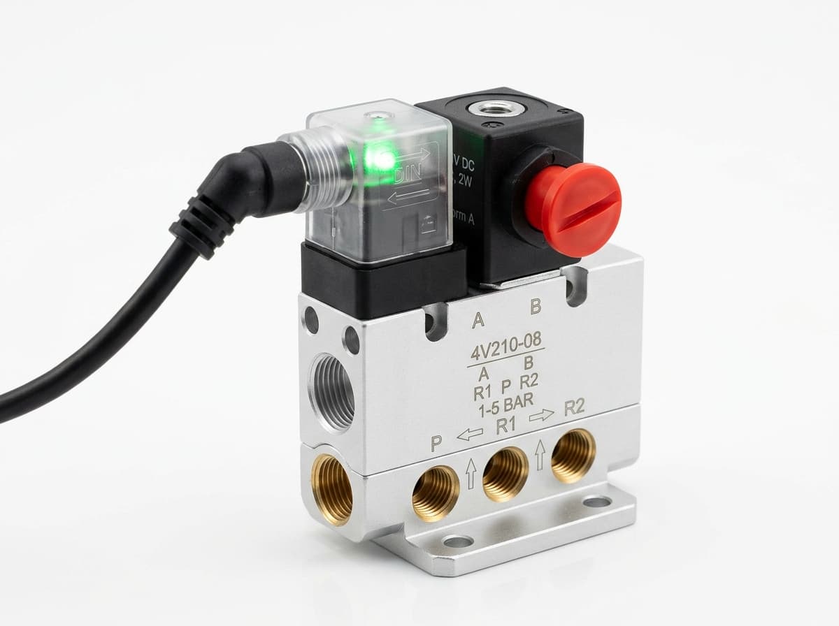
Directional control valves
Switch the pneumatic circuit. Select the valve function, flow capacity, port size and control signal for the application.
Product-group reference image
PneuPart SL speed controllers
Control actuator air flow. Confirm thread, tube size, flow direction and required flow rate.
Product-group reference image
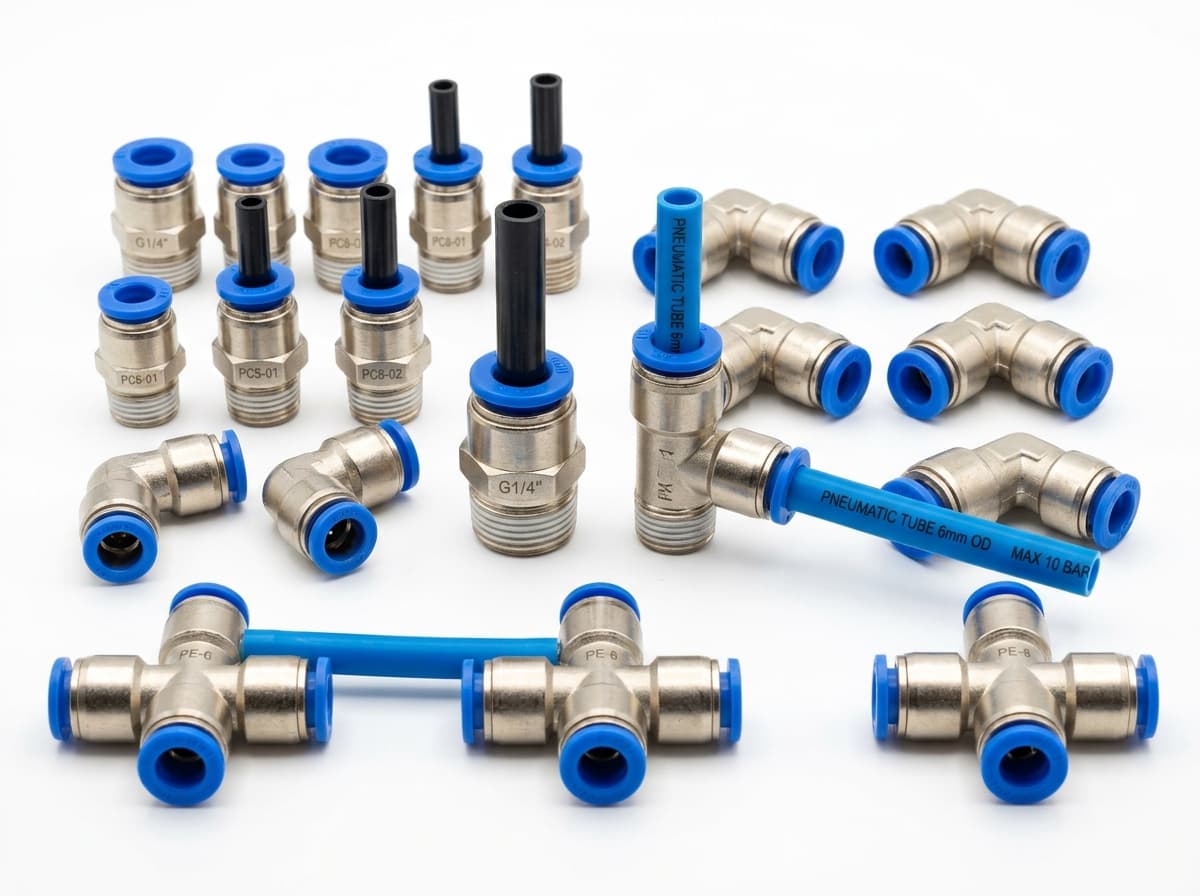
PneuPart tube fittings
Connect tubing to a valve or actuator. Match tube outside diameter, port thread and seal type.
Product-group reference image
PneuPart pneumatic tubing
Run air lines between fittings and components. Confirm outside diameter, bend radius, pressure and temperature.
Planning a Complete Circuit or Multi-Item BOM?
Send your parts list, connection sizes and operating conditions for a matching check and combined quotation.