Find your HFKL type
Choose a type; send a model or photo if unsure.
Request a QuoteSend a Photo — We’ll Help Identify It →
Send the model, quantity and destination. For multiple items, attach a parts list or BOM.
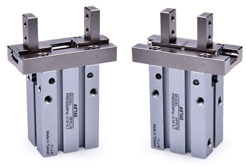
Guided long-stroke parallel grippers with integrated roller guide and bore 10/16/20/25....
Official reference
Based on manufacturer documentation
Model support
For model confirmation
Parts lists
Code, photo, or BOM
Availability / lead time
By model and quantity
Guided long-stroke parallel grippers with integrated roller guide and bore 10/16/20/25. Identify double or single action first, then confirm finger mounting, workpiece geometry and force at the actual pressure and gripping point before quotation.
Know your model? Send it with the quantity for a quote. Not sure? Start with a photo, label or description. We help identify the model and clarify availability and lead time. Mixed parts lists are welcome too.
Choose a type; send a model or photo if unsure.
Send the model, quantity and destination. For multiple items, attach a parts list or BOM.
Match a Guided Gripper and Function
AirTAC HFKL specifications official family reference
Helpful for Model Matching:
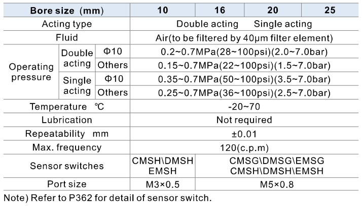
| Function / guide | HFKL double acting; HFSKL single acting normally closed; HFTKL single acting normally open. Integrated linear guide roller, long travel and positioning pin. Do not confuse with HFK shorter-stroke models. |
| Code / mounting | Bores 10/16/20/25; blank standard finger, B side mounting, N through-hole mounting, F bottom mounting. No stroke, S magnet, cushion or PT/G/T thread suffix is published. All include magnet; switches ordered separately. |
| Total travel | Opening/closing stroke, both sides: 8/12/18/22 mm for bores 10/16/20/25. This is total two-finger travel, not travel per finger and not an ordering-code field. |
| Pressure | Double acting: bore 10 0.2–0.7 MPa, others 0.15–0.7. Single acting: bore 10 0.35–0.7 MPa, others 0.25–0.7. Proof pressure is not specified and requires confirmation. |
| Air / temperature / repeatability | 40 μm filtered air; −20 to 70°C; lubrication not required; repeatability ±0.01 mm. Maximum frequency 120 c.p.m. is not jaw speed in mm/s. Use flow control if motion is too fast. |
| Ports / switches | 10 M3×0.5; 16/20/25 M5×0.8. Bore 10 CMSH/DMSH/EMSH; 16/20/25 CMSG/DMSG/EMSG and CMSH/DMSH/EMSH. Square/round switch slots have different matching sensor families; switches need separate confirmation. |
| Force per finger | At 0.5 MPa and gripping point L=20 mm: HFKL External 11/34/45/69 N, Internal 17/45/68/102 N; HFTKL External 7/27/35/55 N; HFSKL table Internal 13/38/59/87 N, External blank. Values are per finger, not sum of fingers, payload kg or a spring-only rating. |
| NC direction / spring boundary | HFSKL table labels force Internal and the normally-closed graph shows internal gripping, with the general title clamping force. This is an internal gripping rating; an external gripping rating is not specified. Confirm pressure-dependent operation. The installation text requires consultation if clamping only by spring force; do not promise fail-safe retention on air loss. |
| Static external loads | Vertical load Fv for 10/16/20/25: 87/147/221/382 N; pitch Mp and yaw My 0.26/0.68/1.32/1.94 N·m; roll Mr 0.53/1.36/2.65/3.88 N·m. Static limits are not dynamic gripping force or payload ratings. Allowable force under moment M depends on actual lever L in metres. |
| L / H / friction | Use function-specific force curves and closed/opened gripping-point range charts. Keep L and eccentric distance H within the curve; choose short/light jaw fittings. Source handling example uses safety factor 4 and friction-dependent force 10–20 times workpiece weight, not 10–20 times mass without gravity. Shock or acceleration needs a larger safety factor. |
| Mounting / workpiece | Use direction-specific body bolt engagement/torque and jaw fitting bolt table. Hold the gripping jaw with a spanner while tightening, not the body. Keep front through-hole screws clear of sensor grooves, provide contact gaps at stroke ends and during reverse motion, insert coaxially and avoid impact. |
| Source labels / material | 25 mm bottom finger drawing on page 269 is wrongly titled side mounting (B type), though ordering image and drawing geometry identify bottom F. Preserve full original drawing and verify actual geometry. Material drawing is based on a certain bore, not a universal BOM. |
Ordering code matching
Code format
[HFKL/HFSKL/HFTKL]-[10/16/20/25]-[blank/B/N/F]Function, bore and finger mounting onlyHFKL20HFSKL16BHFTKL25F| 1Function | 2Bore | 3Finger type |
|---|---|---|
| HFKL double; HFSKL single NC; HFTKL single NO | 10/16/20/25, with fixed total travel 8/12/18/22 mm | Blank standard; B side; N through-hole; F bottom |
If the label is incomplete, send the readable parts together with a photo.
HFKL 20 NHFKLFunction
Double acting guided parallel gripper
20Bore
Bore 20 mm; total travel 18 mm, not a stroke code
NFinger mounting
Through-hole finger mounting; match the complete drawing
Guided long-stroke parallel grippers with integrated roller guide and bore 10/16/20/25. Identify double or single action first, then confirm finger mounting, workpiece geometry and force at the actual pressure and gripping point before quotation.
No. The ordering table uses only family, bore and optional finger type. All include magnet; switches are ordered separately. Stroke is the total travel of both sides.
Confirm force per finger at actual pressure and L/H, friction and external loads. HFSKL publishes internal-gripping force only; spring-only clamping requires consultation.
HFKL
HFKL Add other models, quantities, photos, drawings, or a BOM. One request can cover several product groups.
Build your pneumatic circuit with complementary components. Confirm dimensions and operating conditions before selecting a combination.
Product-group reference image
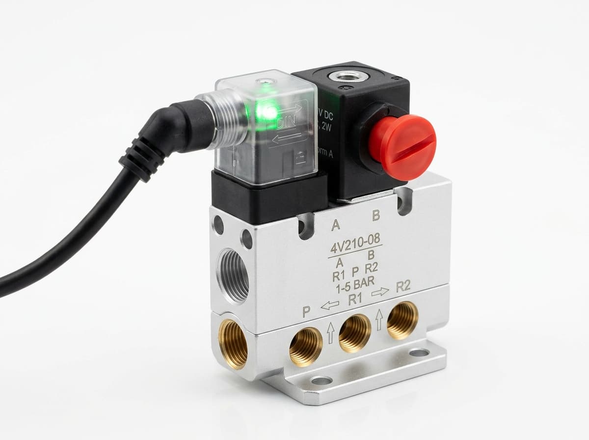
Switch the pneumatic circuit. Select the valve function, flow capacity, port size and control signal for the application.
Product-group reference image
Control actuator air flow. Confirm thread, tube size, flow direction and required flow rate.
Product-group reference image
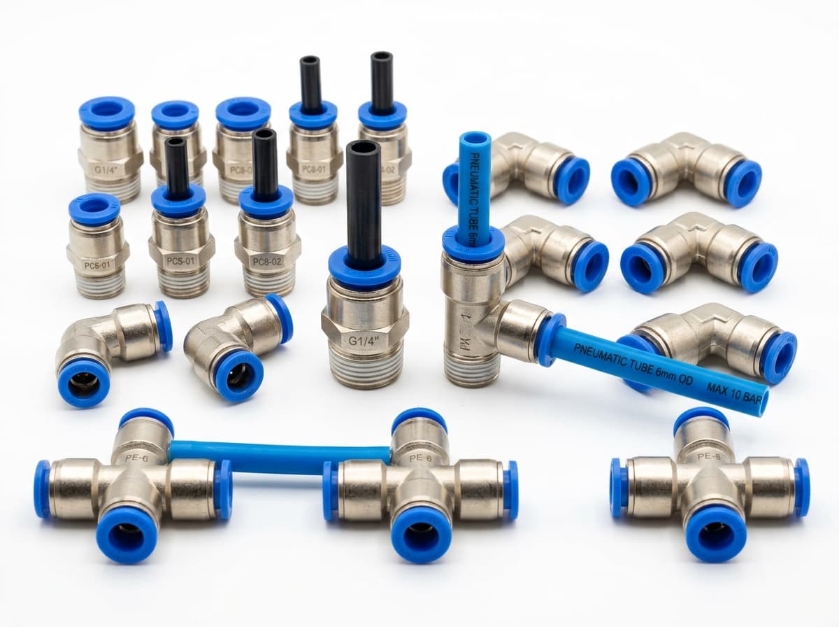
Connect tubing to a valve or actuator. Match tube outside diameter, port thread and seal type.
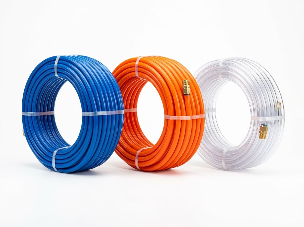
Product-group reference image
Run air lines between fittings and components. Confirm outside diameter, bend radius, pressure and temperature.
Send your parts list, connection sizes and operating conditions for a matching check and combined quotation.