Find your PWC type
Choose a type; send a model or photo if unsure.
PWC
Standard threaded P port
PWL
Push-in tube P port
Send the model, quantity and destination. For multiple items, attach a parts list or BOM.
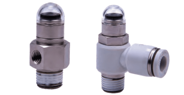
PWC threaded and PWL push-in pneumatic piston indicators show compressed-air signals. Match...
Official reference
Based on manufacturer documentation
Model support
For model confirmation
Parts lists
Code, photo, or BOM
Availability / lead time
By model and quantity
PWC threaded and PWL push-in pneumatic piston indicators show compressed-air signals. Match both P/A interfaces, red or green indication, thread type and operating pressure; send the code or installation photo for quotation.
Know your model? Send it with the quantity for a quote. Not sure? Start with a photo, label or description. We help identify the model and clarify availability and lead time. Mixed parts lists are welcome too.
Choose a type; send a model or photo if unsure.
PWC
Standard threaded P port
PWL
Push-in tube P port
Send the model, quantity and destination. For multiple items, attach a parts list or BOM.
Match a PWC/PWL Pneumatic Indicator Code
AirTAC PWC/PWL specification
Helpful for Model Matching:
| Identity and mechanism | Pneumatic piston indicator for compressed-air signal presence. No electric lamp, voltage, LED, magnetic switch or pressure-gauge output is specified. Red and green are ordering colors, not an inferred automatic two-color state display. |
| PWC standard threaded form | PWC has an M5 × 0.8 female P port and M5 × 0.8, 1/8 or 1/4 male A port. Two interface fields are required: PWCM5M5, PWCM501 or PWCM502 before color/thread suffixes. |
| PWL push-in form | PWL P port takes nylon or PU tube: 4 mm allows M5/01 A ports; 6 mm allows M5/01/02; 8 mm allows 01/02. 01 = 1/8 and 02 = 1/4 male A thread. Do not validate 4 mm × 1/4 or 8 mm × M5. |
| Color and thread codes | R = red, GN = green. Blank thread field = PT, G = G thread, T = NPT for fractional A ports. M5 thread field must remain blank. G alone is not the green color code. |
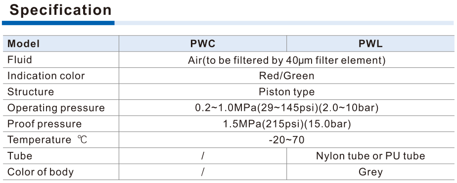
| Working medium and pressure | Air filtered through a 40 μm filter element. Operating pressure 0.2–1.0 MPa (2–10 bar); proof pressure 1.5 MPa (15 bar). Proof pressure is not a continuous operating rating or a calibrated switching threshold. |
| Temperature and body | Published temperature −20 to +70°C. Nylon viewing window, nickel-plated brass body; PWL has grey plastic push-in body. The catalogue supplies no IP rating, switching delay or numeric flow rate. |
| Installation and drawing boundary | Match P/A connection orientation, thread, tube O.D., wrench clearance and viewing position. PWC drawing shows upper M5 × 0.8 / depth 4.5; confirm its mounting use from the actual drawing, not a generic panel-cutout assumption. Parenthesized drawing dimensions are for G-thread models. |
| Inquiry inputs | Send full code or label, PWC/PWL form, both P/A interfaces, tube O.D. if applicable, R/GN color, thread type, pressure, installation photo, quantity and destination. Request availability and fit confirmation. |
Ordering code matching
Code format
PWC M5 [M5/01/02] [R/GN] [blank/G/T]M5 P port and male A port; no thread suffix for M5PWL [4/6/8] [M5/01/02] [R/GN] [blank/G/T]Tube and A port must satisfy interface matrixPWCM501RPWCM5M5GNPWL601GNGPWL802RT| 1Series | 2P port | 3A port | 4Color | 5Thread |
|---|---|---|---|---|
| PWC threaded; PWL push-in. | PWC M5; PWL tube O.D. 4/6/8 mm. | M5/01/02 per published interface matrix. | R red; GN green. | Blank PT; G G; T NPT. M5 requires blank. |
If the label is incomplete, send the readable parts together with a photo.
PWL601R1Series
PWC threaded; PWL push-in.
2P port
PWC M5; PWL tube O.D. 4/6/8 mm.
3A port
M5/01/02 per published interface matrix.
4Color
R red; GN green.
5Thread
Blank PT; G G; T NPT. M5 requires blank.
PWC threaded and PWL push-in pneumatic piston indicators show compressed-air signals. Match both P/A interfaces, red or green indication, thread type and operating pressure; send the code or installation photo for quotation.
It is a pneumatic piston indicator with red or green ordering color. The catalogue gives a 0.2–1.0 MPa operating range, not a voltage or calibrated threshold. Match the two interfaces and installed visibility before quotation.
PWC
PWC Add other models, quantities, photos, drawings, or a BOM. One request can cover several product groups.
Build your pneumatic circuit with complementary components. Confirm dimensions and operating conditions before selecting a combination.

Product-group reference image
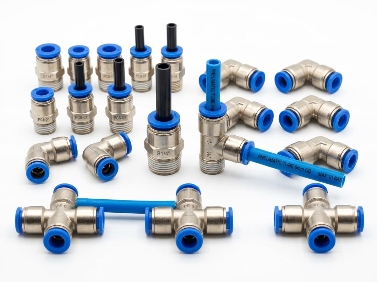
Connect tubing to a valve or actuator. Match tube outside diameter, port thread and seal type.

Product-group reference image
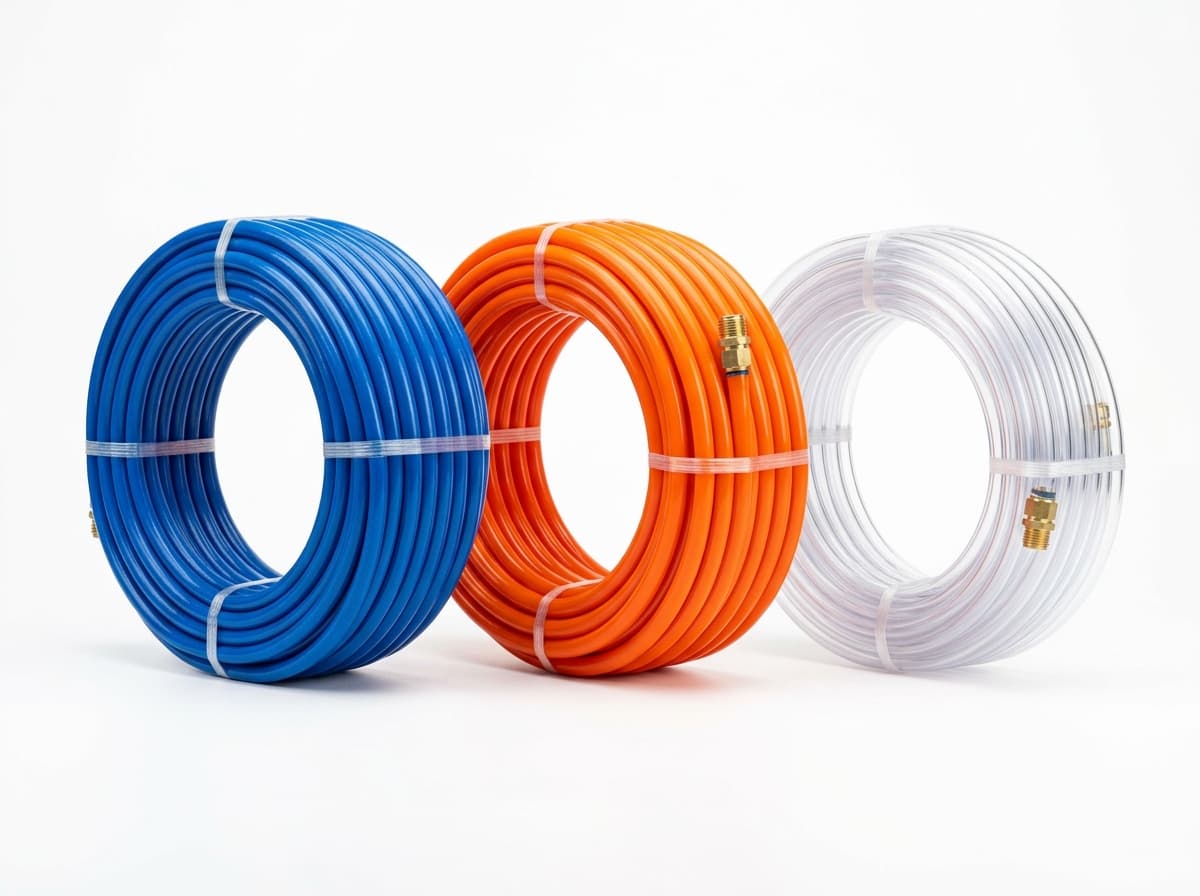
Run air lines between fittings and components. Confirm outside diameter, bend radius, pressure and temperature.

Product-group reference image
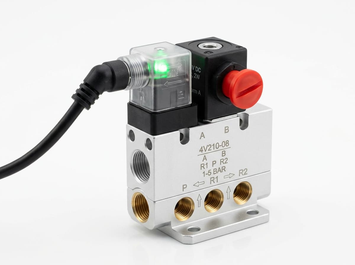
Switch the pneumatic circuit. Select the valve function, flow capacity, port size and control signal for the application.
Send your parts list, connection sizes and operating conditions for a matching check and combined quotation.