Find your HLQ type
Choose a type; send a model or photo if unsure.
HLQ
Standard mounting layout · ball bearings
HLQL
Symmetrical mounting layout · own drawings
Send the model, quantity and destination. For multiple items, attach a parts list or BOM.
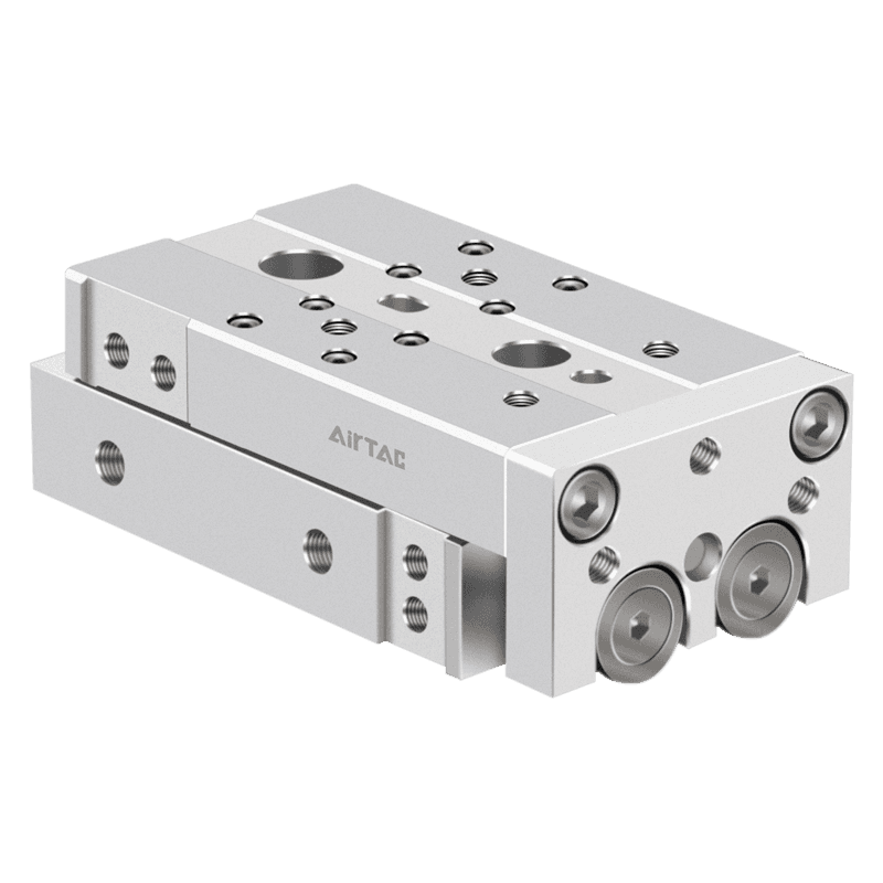
Dual-rod ball-bearing slide tables: standard HLQ and symmetrical HLQL, bores 6–25 mm. Match...
Official reference
Based on manufacturer documentation
Model support
For model confirmation
Parts lists
Code, photo, or BOM
Availability / lead time
By model and quantity
Dual-rod ball-bearing slide tables: standard HLQ and symmetrical HLQL, bores 6–25 mm. Match handedness, listed stroke, extension/retraction adjuster and metric or pipe connection; send model, load, quantity and destination for quotation.
Know your model? Send it with the quantity for a quote. Not sure? Start with a photo, label or description. We help identify the model and clarify availability and lead time. Mixed parts lists are welcome too.
Choose a type; send a model or photo if unsure.
HLQ
Standard mounting layout · ball bearings
HLQL
Symmetrical mounting layout · own drawings
Send the model, quantity and destination. For multiple items, attach a parts list or BOM.
Match an HLQ model code
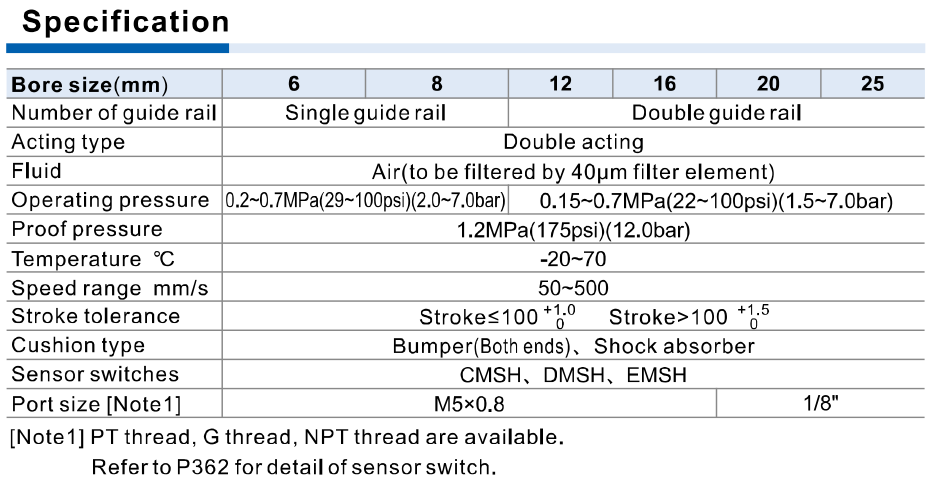
HLQ guide rails pressure ports and sensor specification
Helpful for Model Matching:
| Identity / guide | Double-acting, dual-rod ball-bearing slide-table cylinder. Standard HLQ and symmetrical HLQL. Bores 6/8: single guide rail; 12/16/20/25: double guide rail. |
| Working / proof pressure | 6/8: 0.2–0.7 MPa; 12/16/20/25: 0.15–0.7 MPa. Proof 1.2 MPa is not operating pressure; air filtered by 40 μm element. |
| Temperature / speed | −20 to+70°C; 50–500 mm/s. Installation says meter-out speed control and below 500 mm/s; use the load/energy/moment method for actual selection. |
| Published strokes | 6: 10/20/30/40/50; 8: plus 75; 12: plus 100; 16: plus 125; 20/25: plus 150 mm. Non-standard requests require confirmation. |
| Ports / thread | 6/8/12/16: M 5×0.8 metric, no pipe-thread suffix.20/25: 1/8, blank PT, G G, T NPT. The generic ordering thread box does not convert small-bore M 5 into pipe thread. |
| Magnet / sensors | S: with magnet, the only published magnet field; installation says all are with magnet. CMSH/DMSH/EMSH. Maintain at least 3 mm spacing when units are side by side to avoid sensor malfunction. |
| Adjuster / direction | Blank: no adjuster. A: rubber stoppers both ends; AS: extension; AF: retraction. B: shock absorbers both ends; BS: extension; BF: retraction. Bore 6 excludes B/BS/BF. |
| Applied-load selection | Table 1 maximum allowable applied-load references for 6/8/12/16/20/25: 4/8/15/30/40/70 N, not kg or output thrust. Effective allowance Wa=K×β×Wmax: top mounting K=1, front mounting K=0.6; β depends on average speed. Check actual applied load against Wa. |
| Kinetic energy | Table 1 Emax(J), basic/rubber stopper: 6 0.01; 8 0.024; 12 0.05; 16 0.10; 20 0.13; 25 0.22. Shock absorber: 6 unavailable; 8 0.048; 12 0.10; 16 0.20; 20 0.26; 25 0.44. Available Ea=K×Emax; check moving-load energy, not just mass. |
| Moment and overhang | Check horizontal or vertical dynamic/static pitch, yaw, roll as applicable, using stroke-specific Table 2 and actual L 1/L 2/L 3 overhangs. Sum of applicable moment ratios must be≤1. Calculate the allowable load with the catalogue equations and your actual overhangs. |
| Mounting / fastening | Cylinder mounts in three directions; workpiece top/front mounting. Choose correct HLQ/HLQL drawing. Workpiece bolts at least 0.5 mm shorter than maximum thread depth; hold the slide while fastening to avoid damaging the guide. |
| Shock absorbers | 6: none; 8/12 ACA 0806-1N; 16 ACA 1007-1N; 20 ACA 1210-1N; 25 ACA 1412-1N. Lock-nut torque 1.67/1.67/3.14/3.14/10.8 Nm for 8/12/16/20/25. Bottom screws are not adjustment screws; do not turn them. |
| Accessories / materials | F-HLQ[boresize][A/AS/AF/B/BS/BF] or F-HLQL... are adjuster accessories, not complete cylinder codes; 6 has no B/BS/BF. P 199 says A=AS+AF and B=BS+BF. Internal material list is based on one bore: exact material needs require confirmation. |
| Stroke tolerance | Stroke≤100: +1.0/0 mm; stroke>100: +1.5/0 mm. Dimensional/moment pages remain bore-, stroke- and handedness-specific. |
Ordering code matching
Code format
HLQ[L][bore]×[listed stroke]S[adjuster]-[G/T only20/25]Published magnet and bore-specific end/thread optionsHLQ6×20SASHLQ12×50SAHLQ20×30SAS-GHLQL25×150SBF-T| ①Structure / bore / stroke | ②Magnet / end treatment | ③Ports / threads |
|---|---|---|
| HLQ standard; HLQL symmetrical. 6: 10/20/30/40/50; 8: plus 75; 12: plus 100; 16: plus 125; 20/25: plus 150 mm. Non-standard requests require confirmation. | Blank: no adjuster. A: rubber stoppers both ends; AS: extension; AF: retraction. B: shock absorbers both ends; BS: extension; BF: retraction. Bore 6 excludes B/BS/BF. S magnet required. | 6/8/12/16: M 5×0.8 metric, no pipe-thread suffix.20/25: 1/8, blank PT, G G, T NPT. The generic ordering thread box does not convert small-bore M 5 into pipe thread. |
If the label is incomplete, send the readable parts together with a photo.
HLQ20×30SAS-G①Structure / bore / stroke
HLQ standard; HLQL symmetrical. 6: 10/20/30/40/50; 8: plus 75; 12: plus 100; 16: plus 125; 20/25: plus 150 mm. Non-standard requests require confirmation.
②Magnet / end treatment
Blank: no adjuster. A: rubber stoppers both ends; AS: extension; AF: retraction. B: shock absorbers both ends; BS: extension; BF: retraction. Bore 6 excludes B/BS/BF. S magnet required.
③Ports / threads
6/8/12/16: M 5×0.8 metric, no pipe-thread suffix.20/25: 1/8, blank PT, G G, T NPT. The generic ordering thread box does not convert small-bore M 5 into pipe thread.
Dual-rod ball-bearing slide tables: standard HLQ and symmetrical HLQL, bores 6–25 mm. Match handedness, listed stroke, extension/retraction adjuster and metric or pipe connection; send model, load, quantity and destination for quotation.
No B, BS or BF complete-cylinder option is published for bore 6. Blank/basic or A/AS/AF rubber-stopper options follow the ordering table. Send the end-energy requirement for selection.
HLQL is the symmetrical mounting layout. Use its own bore/stroke drawing and installed port/table orientation. The common ordering scope does not establish drop-in compatibility.
No. Check corrected allowable applied load, energy and static/dynamic moments separately. Include mounting direction, load center, overhang, speed and actual pressure in your inquiry.
HLQ
HLQ Add other models, quantities, photos, drawings, or a BOM. One request can cover several product groups.
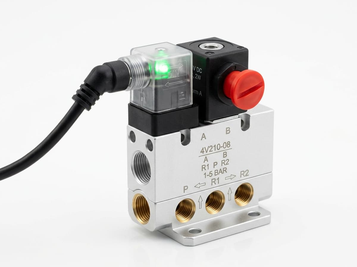
Build your pneumatic circuit with complementary components. Confirm dimensions and operating conditions before selecting a combination.

Product-group reference image
Switch the pneumatic circuit. Select the valve function, flow capacity, port size and control signal for the application.

Product-group reference image
Control actuator air flow. Confirm thread, tube size, flow direction and required flow rate.

Product-group reference image
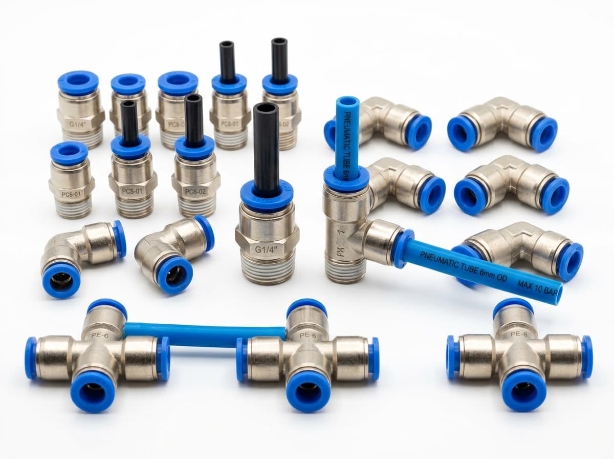
Connect tubing to a valve or actuator. Match tube outside diameter, port thread and seal type.

Product-group reference image
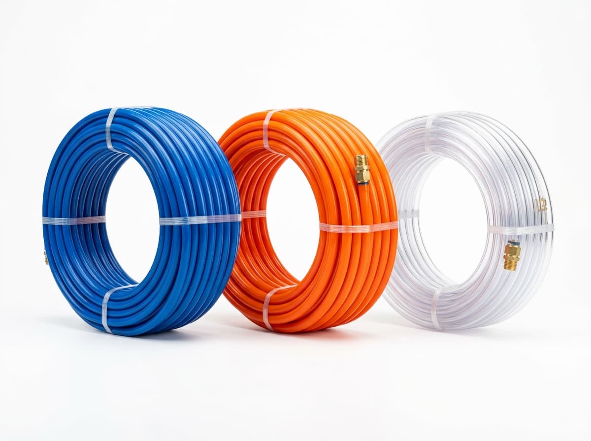
Run air lines between fittings and components. Confirm outside diameter, bend radius, pressure and temperature.
Send your parts list, connection sizes and operating conditions for a matching check and combined quotation.