Find your PSS type
Choose a type; send a model or photo if unsure.
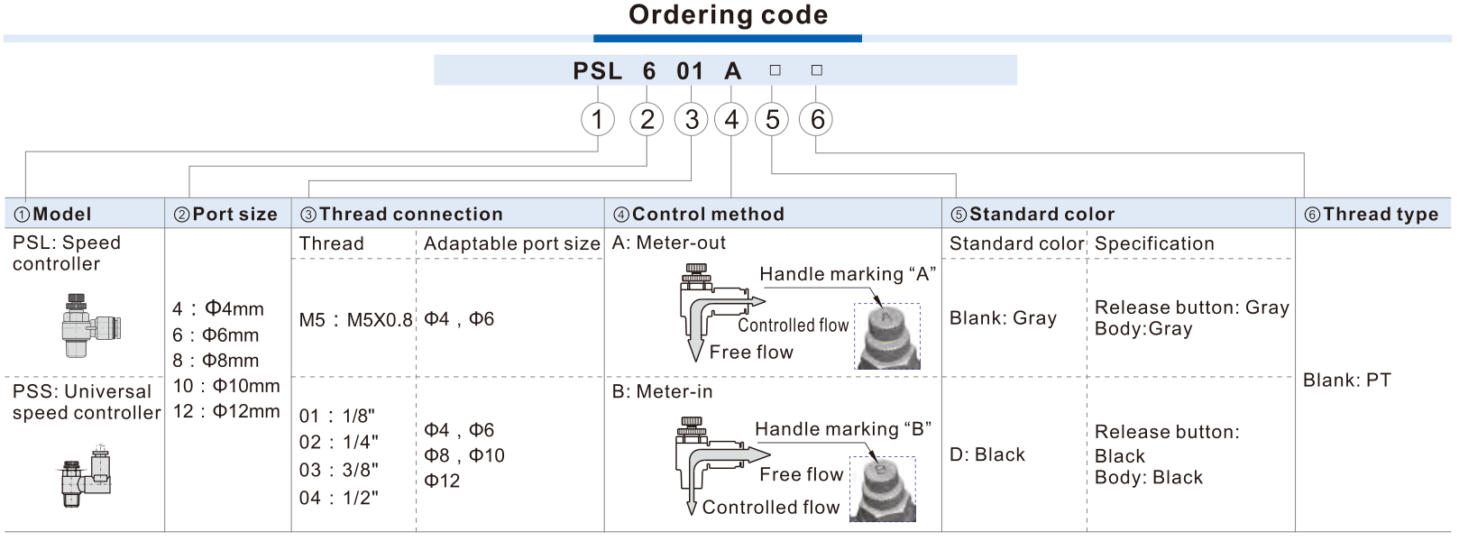
PSS-A
Meter-out; controlled thread→tube
PSS-B
Meter-in; controlled tube→thread
Send the model, quantity and destination. For multiple items, attach a parts list or BOM.

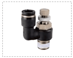
PSS universal speed controllers combine tube-to-thread fittings with360° adjustable tube...
Official reference
Based on manufacturer documentation
Model support
For model confirmation
Parts lists
Code, photo, or BOM
Availability / lead time
By model and quantity
PSS universal speed controllers combine tube-to-thread fittings with360° adjustable tube orientation and A meter-out or B meter-in one-way control. Match the exact nine-pair interface matrix and actual flow direction; request quotation with code and circuit details.
Know your model? Send it with the quantity for a quote. Not sure? Start with a photo, label or description. We help identify the model and clarify availability and lead time. Mixed parts lists are welcome too.
Choose a type; send a model or photo if unsure.
PSS-A
Meter-out; controlled thread→tube
PSS-B
Meter-in; controlled tube→thread
Send the model, quantity and destination. For multiple items, attach a parts list or BOM.
Match a PSS Universal Speed Controller Code
AirTAC PSS ordering
Helpful for Model Matching:
| PSS identity | PSS universal one-way speed controller with tube-to-thread interfaces and360° adjustable tube insertion orientation. It is distinct from inline PSA and elbow PSL. Universal describes orientation, not compatibility with every tube/thread, bidirectional equal regulation or swivel service life. |
| A and B controlled direction | A meter-out: controlled threaded end→tube, free tube→thread. B meter-in: controlled tube→thread, free thread→tube. Use actual actuator circuit and A/B handle marking; do not reverse meanings from mounting appearance. |
| Published interface matrix | PSS4M5, PSS601, PSS602, PSS801, PSS802, PSS1002, PSS1003, PSS1203, PSS1204 only. M5×0.8 with4 mm; PT1/8 with6/8 mm; PT1/4 with6/8/10 mm; PT3/8 with10/12 mm; PT1/2 with12 mm. The wider PSL tube/thread combination matrix does not apply to PSS. |
| Suffix and color | A/B control code required; blank grey or D black release button/body. PT blank thread field; M5 metric. No G/NPT, voltage, omitted control code or extra seal suffix in these sources. |
| Operating limits | 0–1.0 MPa working;1.5 MPa proof;−20 to+70°C ambient/fluid;−750 mmHg vacuum. Soft nylon or polyurethane tube. Proof is not continuous working pressure; actual tube compatibility and circuit conditions require confirmation. |
| Needle control and leakage | Needle clockwise reduces controlled flow/speed; counterclockwise increases. Begin from closed and open slowly for actual actuator commissioning. Source explicitly permits some leakage in closed position: not a zero-leak stop valve, safety isolation or pressure-compensated constant-flow regulator. Do not use pliers or force at adjustment limits. |
| Materials | Nickel-plated brass core/needle, aluminium-alloy cap/rings, PBT plastic body/holder, POM location/interface pieces, NBR seals and stainless spring per source structure. Neither all-metal nor copper-free/stainless body. Published anti-drop design does not establish a safety certification. |
| PSS dimensions | PSS-specific table retains tubeD, threadR, insertionL, adjustableCmax/min and weight for all nine pairs. A/B have same external dimensions. 4M5 C30/27.5 mm,weight8.1 g;601 C41.5/35 mm,19 g;1204 C58.5/51.5 mm,105.8 g. Match knob access,360° tube orientation and wrench clearance, not PSL dimensions. |
| Flow-chart conditions | Shared charts explicitly identify PSS size/thread lines. Controlled flow is graphed against needle turns at0.5 MPa; free flow against inlet pressure inMPa, unitsL/min(ANR). Curves are configuration/condition specific, not guaranteed actuator speed or an exact fully-open capacity for every code. |
| Installation and inquiry inputs | Insert cut tube fully; depressurize before release-button removal. Thread torque/insertion depth referenced to actual fitting instructions, there is no single torque specified for all fittings. Send full code, handleA/B, tube/thread photo, direction/circuit, actuator and speed/duty requirement, pressure/temperature, quantity and destination. |
Ordering code matching
Code format
PSS [4M5/601/602/801/802/1002/1003/1203/1204] [A/B] [blank/D]PSS-specific interface, direction and color matrixPSS4M5APSS601ADPSS802BDPSS1204A| 1Tube OD | 2Thread | 3Control | 4Color |
|---|---|---|---|
| 4/6/8/10/12 mm per PSS-specific matrix. | M5 or PT01/02/03/04; only nine published pairs. | A meter-out; B meter-in; direction must match actual circuit. | Blank grey; D black. |
If the label is incomplete, send the readable parts together with a photo.
PSS802BD1Tube OD
4/6/8/10/12 mm per PSS-specific matrix.
2Thread
M5 or PT01/02/03/04; only nine published pairs.
3Control
A meter-out; B meter-in; direction must match actual circuit.
4Color
Blank grey; D black.
PSS universal speed controllers combine tube-to-thread fittings with360° adjustable tube orientation and A meter-out or B meter-in one-way control. Match the exact nine-pair interface matrix and actual flow direction; request quotation with code and circuit details.
The source explicitly allows some closed-position leakage and does not design it as a zero-leak stop valve. Needle setting and actual pressure/load/circuit influence flow and speed. Confirm A/B direction and commissioning requirements; no constant-flow or safety-isolation guarantee.
PSS
PSS Add other models, quantities, photos, drawings, or a BOM. One request can cover several product groups.
Build your pneumatic circuit with complementary components. Confirm dimensions and operating conditions before selecting a combination.

Product-group reference image
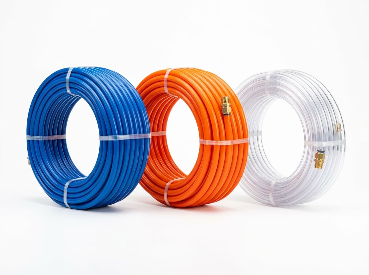
Run air lines between fittings and components. Confirm outside diameter, bend radius, pressure and temperature.

Product-group reference image
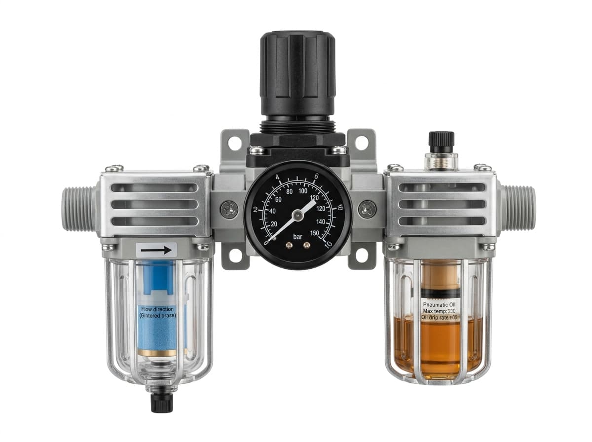
Filter and regulate supply air. Confirm filtration, pressure range and flow requirements for the connected equipment.

Product-group reference image
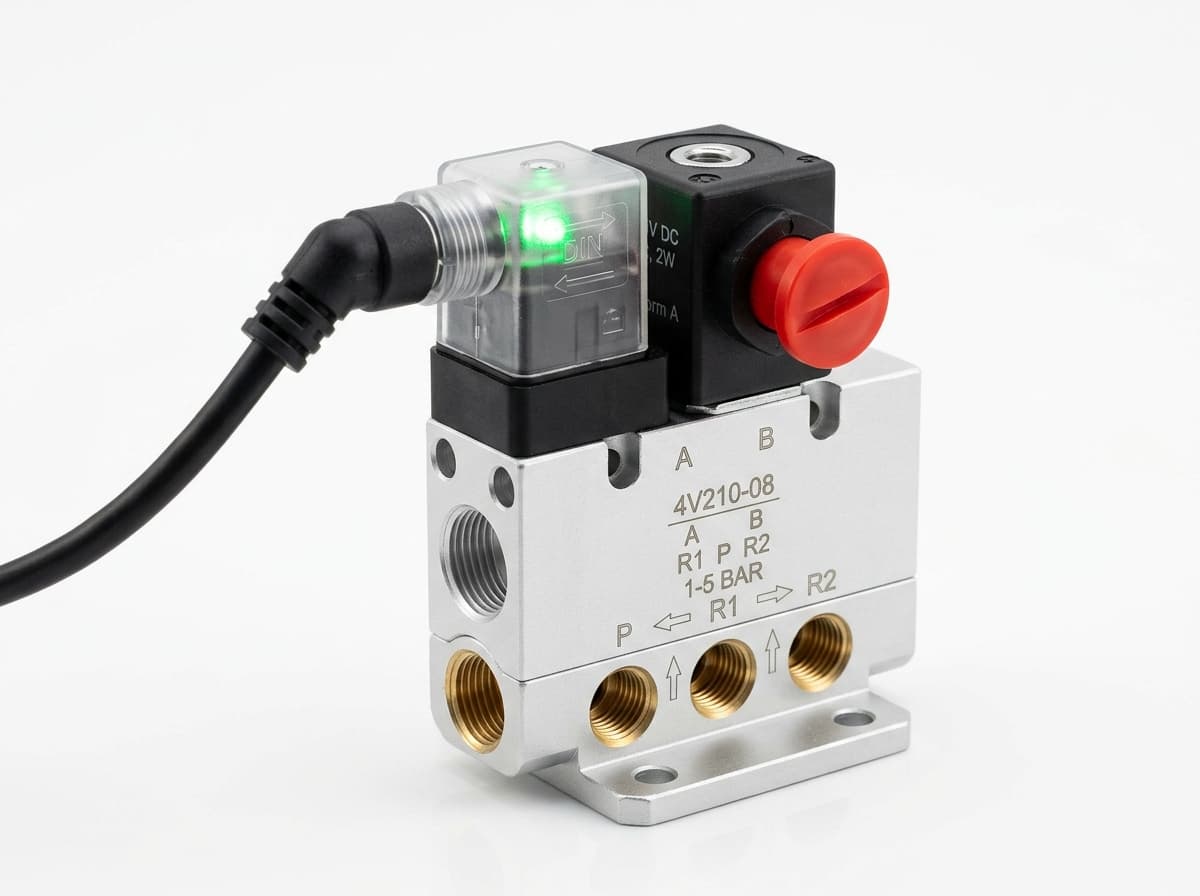
Switch the pneumatic circuit. Select the valve function, flow capacity, port size and control signal for the application.
Send your parts list, connection sizes and operating conditions for a matching check and combined quotation.