AirTAC BSAID Double-Rod Locking Cylinders
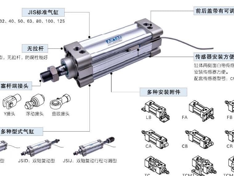
BSAID is the double-rod locking member of the BSAI ISO15552 family; confirm both rod ends and...
Official reference
Based on manufacturer documentation
Model support
For model confirmation
Parts lists
Code, photo, or BOM
Availability / lead time
By model and quantity
Sourcing route & inquiry details
BSAID is the double-rod locking member of the BSAI ISO15552 family; confirm both rod ends and the separate locking circuit. Match bore, listed stroke, magnet and supported mounting, then send the lock circuit and actual static load for quotation and holding confirmation. Static holding data does not approve dynamic braking or safety use.
Know your model? Send it with the quantity for a quote. Not sure? Start with a photo, label or description. We help identify the model and clarify availability and lead time. Mixed parts lists are welcome too.
Match a BSAI Model and Holding Requirement
Part of the BSAI Series family.
View family overview →Installation Drawings & Technical Specifications
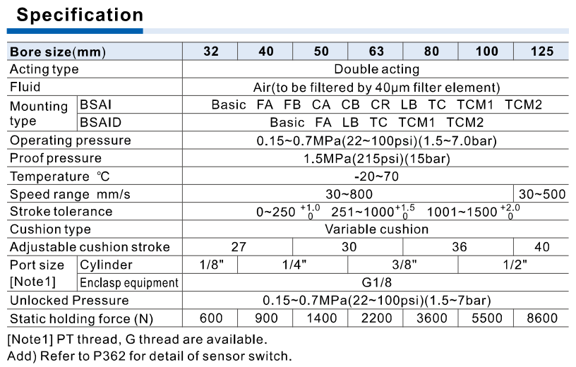
AirTAC BSAID specification official reference
Helpful for Model Matching:
- Complete model or original label
- Listed bore/stroke, magnet and supported mounting
- Lock/release circuit and actual static load/holding direction
- Cylinder ports versus G1/8 locking port; rod and installed clearance
- Accessory/sensor codes, quantity and destination
- Match single versus double rod; BSAID unspecified dimensions follow BSAI.
- Confirm lock G1/8 independent of main-cylinder PT/G port.
- Check lock circuit, static load and exact mounting/accessory pairing.
- Use bore-specific standard stroke and speed; no dynamic brake inference.
Catalogue Technical Specifications
| Identity / lock | BSAI is the SAI ISO15552 double-acting cylinder with added locking structure. BSAID is its double-rod member, with both rod ends requiring clearance. The source says it can lock at random positions within stroke and lock state is unrelated to piston movement direction; it does not publish safety certification or dynamic brake capacity. |
| Standard strokes / 32 boundary | 32 standard row explicitly lists 25/50/75/80/100/125/150/160/175/200/250/300/350/400/450/500 mm, though max column says 700. 600/700 for bore 32 require confirmation. 40 adds 600/700/800; 50/63/80/100/125 add 600/700/800/900/1000. Non-standard strokes require consultation. |
| Pressure / unlock | Cylinder operating and unlocked pressure both 0.15–0.7 MPa; proof 1.5 MPa. SAI working-pressure limits do not apply to BSAI; proof pressure is not an operating pressure. Confirm actual locking/release pneumatic circuit and load state. |
| Cylinder / lock ports | Cylinder ports: 32 1/8; 40/50 1/4; 63/80 3/8; 100/125 1/2. Cylinder thread blank PT or G, no NPT T. Locking equipment port is fixed G1/8 across bores, distinct from main-cylinder thread/size. |
| Static holding force | 32/40/50/63/80/100/125 static holding force 600/900/1400/2200/3600/5500/8600 N. This is not cylinder thrust, TC bracket holding force, dynamic stopping force, payload kg or a certified fail-safe function. |
| Speed / temperature / air | 32–100 speed 30–800 mm/s; 125 speed 30–500 mm/s. Air through 40 μm filter; −20 to 70°C. Lubrication requirements for BSAI need separate confirmation; the generic SAI statement does not apply. |
| Cushion / tolerance | Variable cushion stroke: 32/40 27 mm; 50/63 30; 80/100 36; 125 40. Stroke tolerance: 0–250 +1.0/0 mm, 251–1000 +1.5/0, 1001–1500 +2.0/0. The tolerance row does not make 1001–1500 standard strokes. |
| Mounting boundary | BSAI basic/FA/FB/CA/CB/CR/LB/TC; BSAID basic/FA/LB/TC. Both list TCM1/TCM2 mating bracket scope in specs/accessory matrix. CR used with CB; TC used with TCM1/TCM2. FTC specifically unavailable to BSAI/BSAID in accessory matrix. Temperature, seal or knuckle suffixes are not complete-cylinder ordering options here. |
| Magnet / accessories | Blank without magnet or S with magnet. CMSE/DMSE are compatible only with the magnet option in the accessory matrix; source refers detailed switch specs to P362. I/Y/U/F knuckles and F-series mounting parts are separate accessories, not inferred cylinder suffixes. |
| Dimensions / material | BSAID total A+2×stroke, opposite rod dimensions AF+stroke/DA+stroke; unspecified dimensions follow BSAI. Magnet dimensions same as non-magnet. BSAID drawing table only repeats selected dimensions. Lock module material drawing is based on a certain bore, not universal BOM. |
| TC bracket force | TC bracket accessory static holding and tightening values are separate from the cylinder lock holding table. Do not substitute bracket 800/1200/2000/3000/5000/8000/12000 N for BSAI lock force. Follow size-specific staged black/white stop-screw tightening instructions. |
Ordering Codes, Fit Verification & Specifications
Ordering code matching
Match each code segment
Code format
BSAID-[bore]×[listed stroke]-[S]-[supported mounting]-[G]Blank magnet and PT published; mounting scope is model-specificBSAID40×100SFABSAID80×50SBSAID125×100SG| 1Model / bore | 2Standard stroke | 3Magnet / mounting | 4Thread |
|---|---|---|---|
| BSAI single rod; BSAID double rod; 32/40/50/63/80/100/125 | Use bore-specific listed strokes; 32 max700 but row ends500, confirm600/700 | Blank no magnet, S magnet; double rod excludes FB/CA/CB/CR; FTC unavailable | Blank PT or G for cylinder; lock port G1/8 fixed |
Quick check
Can static holding force be used as dynamic braking capacity?
No dynamic stopping or safety certification is published here. Confirm the actual lock circuit, motion state and static load before selecting the assembly.
Can BSAI32 be automatically matched at 600 or 700 mm?
The maximum column says 700, but its explicit standard list stops at 500. Send the original requirement for confirmation. The SAI standard-stroke list does not apply to this model.
BSAID
Include this series in a project RFQ
BSAID Add other models, quantities, photos, drawings, or a BOM. One request can cover several product groups.
Products to use together
Build your pneumatic circuit with complementary components. Confirm dimensions and operating conditions before selecting a combination.
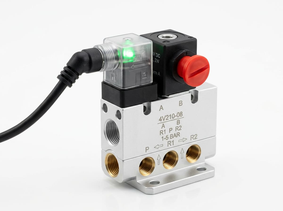
Product-group reference image
Directional control valves
Switch the pneumatic circuit. Select the valve function, flow capacity, port size and control signal for the application.
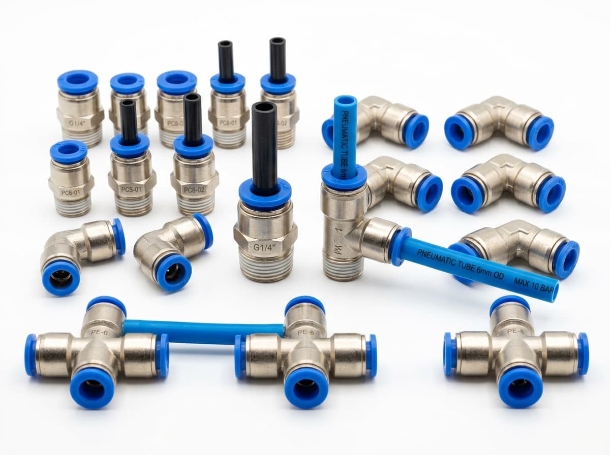
Product-group reference image
PneuPart SL speed controllers
Control actuator air flow. Confirm thread, tube size, flow direction and required flow rate.
Product-group reference image
PneuPart tube fittings
Connect tubing to a valve or actuator. Match tube outside diameter, port thread and seal type.
Product-group reference image
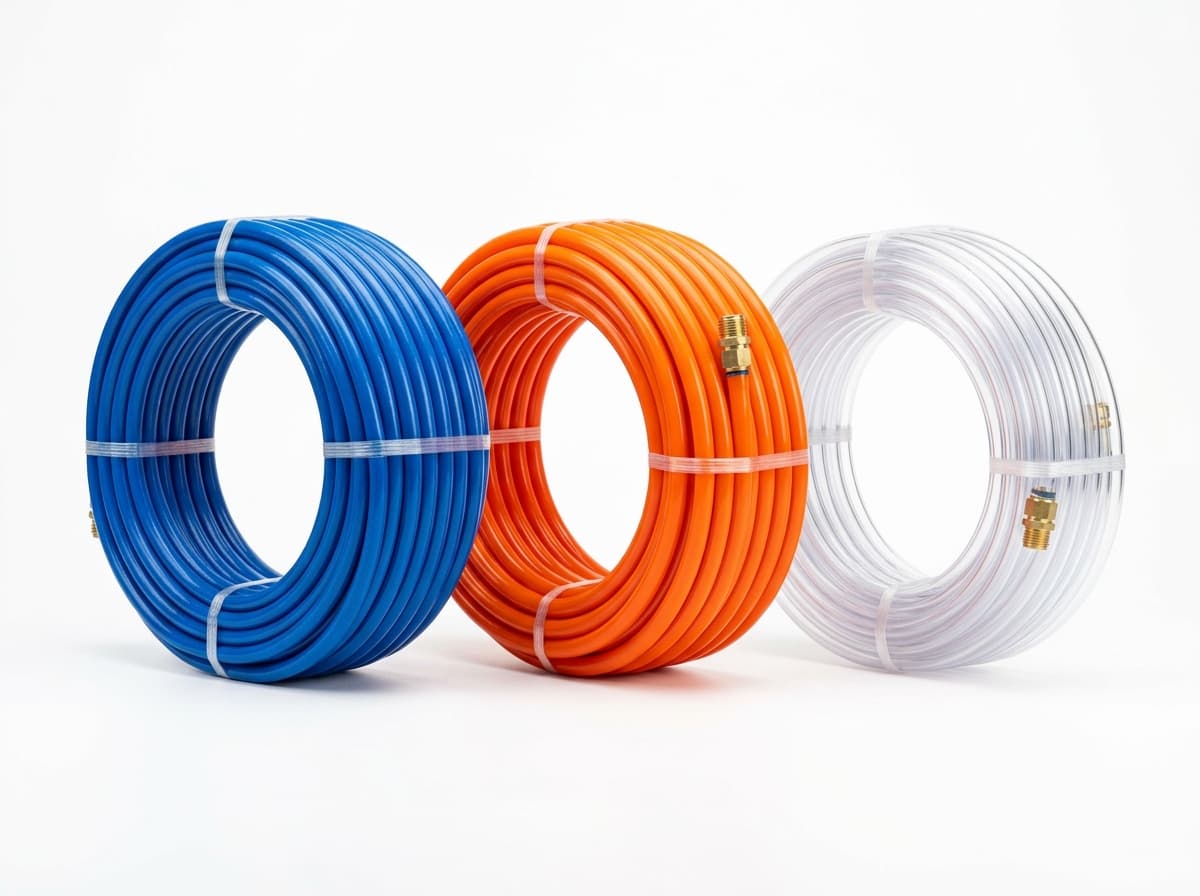
PneuPart pneumatic tubing
Run air lines between fittings and components. Confirm outside diameter, bend radius, pressure and temperature.
Planning a Complete Circuit or Multi-Item BOM?
Send your parts list, connection sizes and operating conditions for a matching check and combined quotation.