AirTAC SED Double-Rod Standard Cylinders
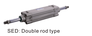
AirTAC SED double-rod standard cylinders. Confirm double acting,double rod or adjustable...
Official reference
Based on manufacturer documentation
Model support
For model confirmation
Parts lists
Code, photo, or BOM
Availability / lead time
By model and quantity
Sourcing route & inquiry details
AirTAC SED double-rod standard cylinders. Confirm double acting,double rod or adjustable travel before matching fit. Send code,label or installed drawing with bore,stroke,mounting,quantity and destination for quotation.
Know your model? Send it with the quantity for a quote. Not sure? Start with a photo, label or description. We help identify the model and clarify availability and lead time. Mixed parts lists are welcome too.
Match an SE / BSE cylinder
Part of the SE Series family.
View family overview →Installation Drawings & Technical Specifications
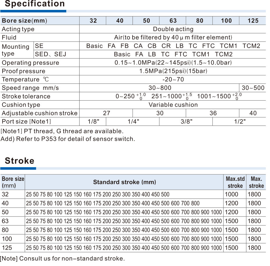
AirTAC SED official se specification strokes
Helpful for Model Matching:
- Full code,label or installed drawing
- Bore,main stroke andadjustment if SEJ
- Magnet,mounting andthread
- Rod/seal version forSE orrelease port/pressure for BSE
- Load,speed,environment and control sequence
- Quantity and destination
- Confirm actualfamily/function,installed length and mount
- Check bore,stroke,adjustment,rod/thread and magnet
- ForBSE verify static load,pressure balance and release timing
- Confirm construction-specific accessory compatibility
Catalogue Technical Specifications
| Construction / standards | SE profile aluminium standard cylinder,no tie rods;ISO15552/VDMA24562. SED double rod;SEJ double rod with adjustable stroke. All double acting. Bore32/40/50/63/80/100/125mm. ISO conformity alone is not guaranteed drop-in interchangeability. |
| Operating conditions | Filtered air40μm or finer;operating pressure0.15–1.0MPa;proof1.5MPa is not continuous service pressure. Standard temperature−20to70°C. Speed30–800mm/s for32–100;125 bore30–500mm/s. Adjustable pneumatic cushion at both ends;side loading and contamination require application review. |
| Published strokes | 32:25/50/75/80/100/125/150/160/175/200/250/300/350/400/450/500;40 adds600/700/800;50–125 add600/700/800/900/1000. These are standard code-matching strokes,not all buildable strokes. English max standard32=1000,40/50=1200,63–125=1500;newerChinese32/40=1000,50–125=1500. Both give maximum1800 by consultation. This source-version conflict and nonlisted strokes require confirmation;only standard strokes listed in both catalogues can be matched directly. |
| SE ordering | SE/SED/SEJ[bore][rod]×[stroke][-adjustment][S][mount][seal][G]. Blank rod medium carbon steel;A SUS420J2;B SUS304;English source alsoC SUS316,absent in newerChinese matrix,confirm source/version forC. Blank no magnet;S magnet. Blank sealTPU;H Viton;N NBR. BlankPT/G G-thread;noNPT code. |
| SEJ adjustment | SEJ alone requires10/20/30/40/50/75/100mm adjustment field following main stroke;it is double-rod adjustable travel,not a single-rod cylinder with arbitrary negative stroke. Both main and adjustment lengths affect installed envelope. |
| Ports / rod interface | Bore32 port1/8;40/50 port1/4;63/80 port3/8;100/125 port1/2. Rod threads32 M10×1.25;40 M12×1.25;50/63 M16×1.5;80 M20×1.5;100 M20×1.5;125 M27×2. Match end-face holes,mounting centres,port orientation and total-length formula. |
| Mounting / accessories | SE blank/LB/FA/FB/CA/CB/CR/FTC/TC;SED/SEJ blank/LB/FA/FTC/TC. CR cannot be used alone;requires CB. FTC/TC operate withTCM1/TCM2 and installation position not freely adjustable. The official compatibility table lists both F-SI and F-SE accessory prefixes; compatibility depends on the exact table entry, not the prefix alone. |
| Sensors / magnet | Three sensor grooves;CMSE/DMSE named in this source. Sensor use requires S magnet;do not imply standard blank magnet or included sensor. Magnet and nonmagnet external dimensions same as table;thread and mount still need confirmation. |
| Forces / cushion | Theoretical thrust table inN,depends on actual pressure and push/pull area;not guaranteed usable load. Rod diameter32/40/50/63/80/100/125:12/16/20/20/25/25/32mm. Cushion stroke27mm for32/40;30 for50/63;36 for80/100;40 for125. |
| TC clamp force versus locking | TC bracket static clamp table800/1200/2000/3000/5000/8000/12000N and torque2–3/4–6/4–6/7–12/12–20/12–20/18–30N·m by bore. This is mounting-bracket clamp force,not BSE rod holding force or cylinder output. Never use it as BSE brake rating. |
Ordering Codes, Fit Verification & Specifications
Ordering code matching
Match each code segment
Code format
SE/SED/SEJ [bore][rod]×[stroke][-adjustment][S][mount][seal][G]Construction-specific field limits andcustom strokes require confirmationSED80BX100SLBHG| 1Family / function | 2Bore / stroke | 3Material / adjustment | 4Magnet / mount | 5Threads / lock release |
|---|---|---|---|---|
| SE baseline;SED double rod;SEJ double rod adjustable;BSE/BSED static-locking independent family. | 32/40/50/63/80/100/125;only published standard combinations auto-matched. | SE rod A/B/C English-only C,seals H/N;SEJ adjustment mandatory;BSE has neither rod nor seal optionalfield. | Blank no magnet/S;mounting options vary by construction. | Cylinder blankPT/G;BSE separate releaseG1/8;noNPT. |
Quick check
Can BSE stop a moving load andcan standard SE dimensions confirm replacement?
BSE is a static rod-locking cylinder;only engage the lock after motion stops,then equalize chamber pressure before release. It is not a dynamic brake orconfirmed safety stop. StandardSE,SED,SEJ andlocking BSE/BSED have different envelopes,ports and mounts;send actual drawing/code,load and control circuit for confirmation.
SED
Include this series in a project RFQ
SED Add other models, quantities, photos, drawings, or a BOM. One request can cover several product groups.
Products to use together
Build your pneumatic circuit with complementary components. Confirm dimensions and operating conditions before selecting a combination.
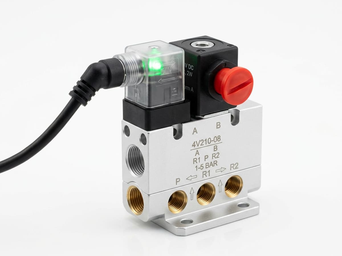
Product-group reference image
Directional control valves
Switch the pneumatic circuit. Select the valve function, flow capacity, port size and control signal for the application.
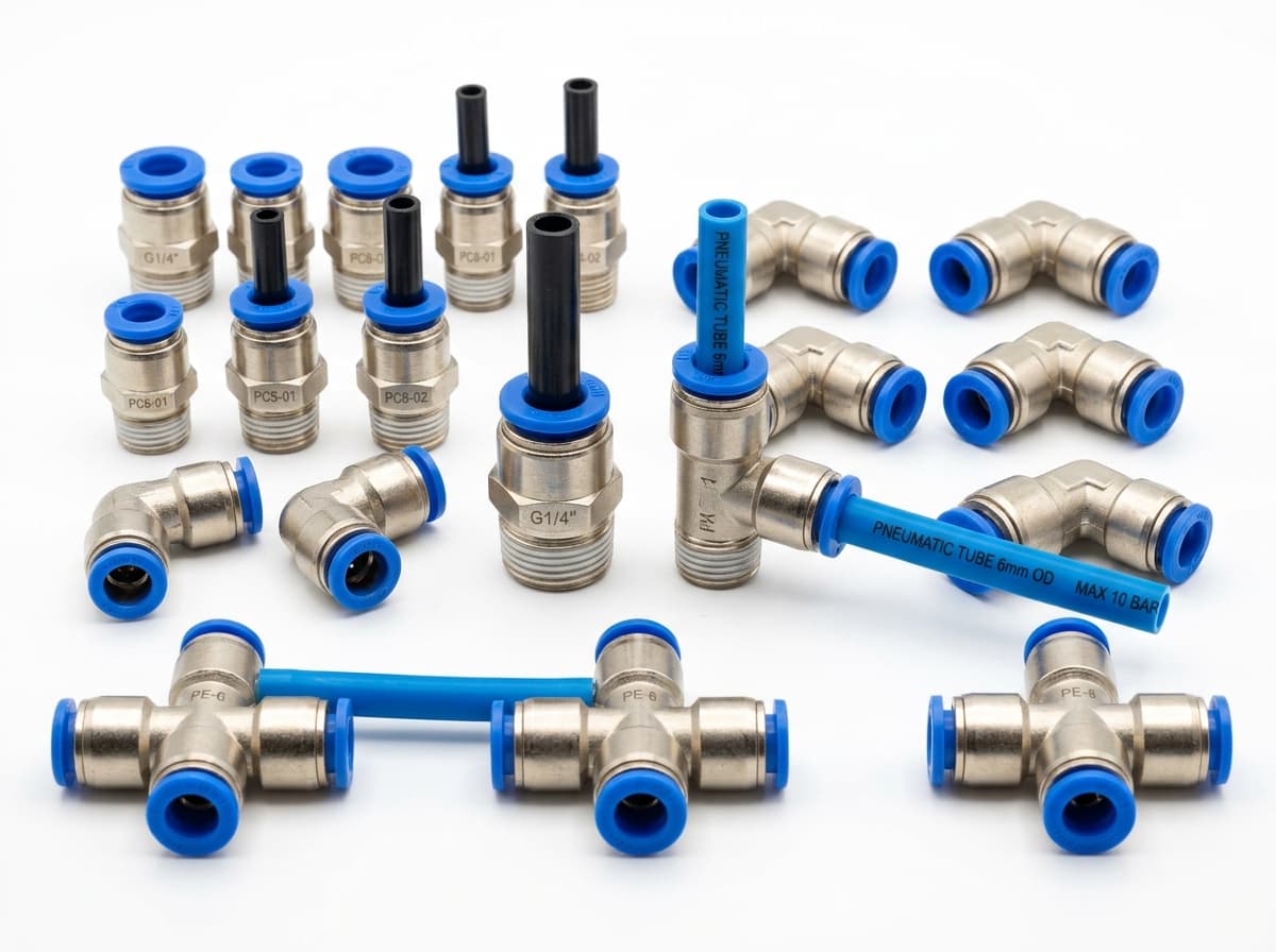
Product-group reference image
PneuPart SL speed controllers
Control actuator air flow. Confirm thread, tube size, flow direction and required flow rate.
Product-group reference image
PneuPart tube fittings
Connect tubing to a valve or actuator. Match tube outside diameter, port thread and seal type.
Product-group reference image
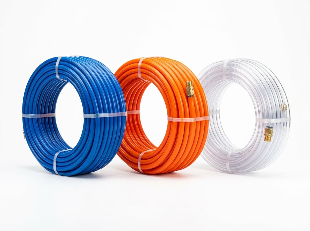
PneuPart pneumatic tubing
Run air lines between fittings and components. Confirm outside diameter, bend radius, pressure and temperature.
Planning a Complete Circuit or Multi-Item BOM?
Send your parts list, connection sizes and operating conditions for a matching check and combined quotation.