AirTAC SAIF Cylinders with Integrated Solenoid Valve
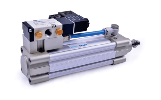
Integrated 4M solenoid valve cylinder. Confirm bore/stroke, valve port, voltage,...
Official reference
Based on manufacturer documentation
Model support
For model confirmation
Parts lists
Code, photo, or BOM
Availability / lead time
By model and quantity
Sourcing route & inquiry details
Integrated 4M solenoid valve cylinder. Confirm bore/stroke, valve port, voltage, terminal/grommet and energized motion. Send full code, label or installation drawing with quantity and destination for quotation.
Know your model? Send it with the quantity for a quote. Not sure? Start with a photo, label or description. We help identify the model and clarify availability and lead time. Mixed parts lists are welcome too.
Match an SAI cylinder model
Part of the SAI Series family.
View family overview →Installation Drawings & Technical Specifications
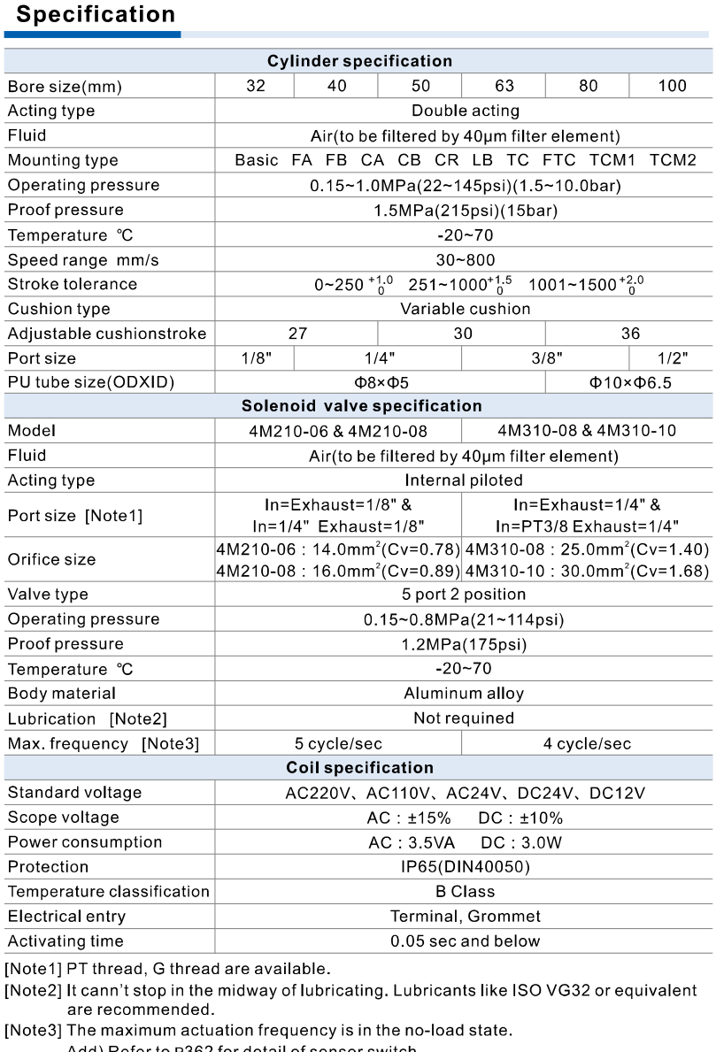
AirTAC SAIF official saif specifications
Helpful for Model Matching:
- Full model code or label
- Bore, working stroke and separate adjustment
- Mounting and rod-end / port drawing
- Magnet, seal and temperature where published
- Lock position or valve voltage/port/motion where applicable
- Quantity and destination
- Confirm functional derivative and its own dimensions
- Confirm working stroke, adjustment and mounting
- Separate rod end, cylinder port and valve port
- Check lock/valve and large-bore trunnion conditions
Catalogue Technical Specifications
| Cylinder pressure / proof | Operating 0.15–1.0 MPa; proof 1.5 MPa. Proof is not continuous operating pressure. |
| Medium / temperature | 40 μm filtered air; −20–70°C; double acting; adjustable pneumatic cushion. |
| Speed | 32–125: 30–800 mm/s; 160/200: 30–500 mm/s. Apply only to the current variant bore range. |
| Cylinder ports | 32: 1/8; 40/50: 1/4; 63/80: 3/8; 100/125: 1/2; 160/200: 3/4. Blank PT / optional G; no NPT field. |
| Rod end | 32: M10×1.25; 40: M12×1.25; 50/63: M16×1.5; 80/100: M20×1.5; 125: M27×2; 160/200: M36×2. Separate from air port. |
| Magnet / switch | Blank without magnet; S with magnet; CMSE / DMSE switches separately selected. Magnetic and non-magnetic dimensions are the same. |
| Mounting accessories | CR must be used with CB, not alone. FTC / TC use TCM1 / TCM2. TC 160/200 is factory installed on the barrel; position cannot be adjusted arbitrarily and cannot be assumed to retrofit a cylinder ordered without TC. TCM1/2 positions for 160/200 cannot be adjusted arbitrarily. |
| Fit / force | ISO15552, originally ISO6431. Confirm installed dimensions, rod-end, load, side loads and cushion. ISO alone does not guarantee interchangeability. Thrust is N at specified pressure, not payload kg. |
| Stroke tolerance | 0–250: +1/0; 251–1000: +1.5/0; 1001–1500: +2/0 mm. No extrapolation above 1500 mm. |
| Bore / strokes | 32/40/50/63/80/100 only. Minimum stroke 50 mm; TC minimum 125 mm. Enumerated strokes follow SAI but start at 50 mm. Maximum standard 32: 1000; 40/50: 1200; 63/80/100: 1500 mm; maximum stroke 1800 mm. Unlisted strokes require confirmation. |
| Assembly pressure | Cylinder 0.15–1.0 MPa / proof 1.5 MPa; valve 0.15–0.8 MPa / proof 1.2 MPa. Complete assembly must satisfy both; cylinder 1.0 MPa is not valve operating rating. |
| Valve / ports | Internal-pilot 5-port 2-position. 32/40/50: 4M210-06 or -08; 63/80/100: 4M310-08 or -10. 06=1/8, 08=1/4, 10=3/8. Valve port differs from cylinder port. |
| Voltage / entry | A AC220V; B DC24V; C AC110V; E AC24V; F DC12V. Blank terminal / I grommet. No D field. AC ±15%, DC ±10%; AC 3.5 VA, DC 3 W; IP65 DIN40050, class B. |
| Energized motion | Factory default rod retracts when energized; valve can be repositioned to extend with correct seals. Confirm required operation using SAIF drawing; no extra polarity suffix published. |
| Valve speed / tubing | 4M210: 5 cycles/s; 4M310: 4 cycles/s, no-load condition. PU tube 32/40/50 OD8×ID5; 63/80/100 OD10×ID6.5 mm. Valve and cylinder −20–70°C. |
| Mounting / omitted fields | Blank/LB/FA/FB/CA/CB/CR/FTC/TC; optional S magnet and G thread. No SAI rod A/B or seal H/N fields. Valve port and voltage mandatory. |
Ordering Codes, Fit Verification & Specifications
Ordering code matching
Match each code segment
Code format
SAIF50X100S-06BMatch only fields published for this derivativeSAIF50X100S-06BSAIF80X200STC-10AIG| 1Model | 2Bore / main stroke | 3Magnet | 4Mounting | 5Valve port | 6Voltage | 7Electrical entry | 8Thread |
|---|---|---|---|---|---|---|---|
| SAIF functional construction | Use enumerated bore and stroke combinations; unlisted strokes require confirmation. | Blank without magnet; S with magnet. | Blank / LB / FA / FB / CA / CB / CR / FTC / TC. | After hyphen: 06/08 for bore32/40/50; 08/10 for bore63/80/100. | A AC220V; B DC24V; C AC110V; E AC24V; F DC12V. | Blank terminal; I grommet. | Blank PT; G optional. No NPT field. |
Quick check
Which function and interfaces should I confirm?
Integrated 4M solenoid valve cylinder. Confirm bore/stroke, valve port, voltage, terminal/grommet and energized motion. Send full code, label or installation drawing with quantity and destination for quotation. Compare this derivative with its own drawing before replacement; ISO alone does not guarantee fit.
SAIF
Include this series in a project RFQ
SAIF Add other models, quantities, photos, drawings, or a BOM. One request can cover several product groups.
Products to use together
Build your pneumatic circuit with complementary components. Confirm dimensions and operating conditions before selecting a combination.
Product-group reference image
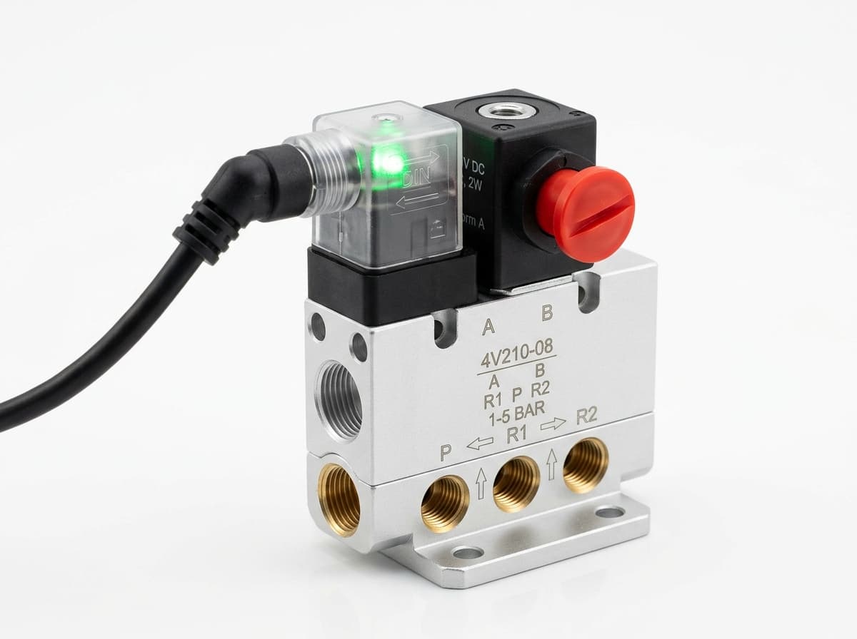
Directional control valves
Switch the pneumatic circuit. Select the valve function, flow capacity, port size and control signal for the application.
Product-group reference image
PneuPart SL speed controllers
Control actuator air flow. Confirm thread, tube size, flow direction and required flow rate.
Product-group reference image
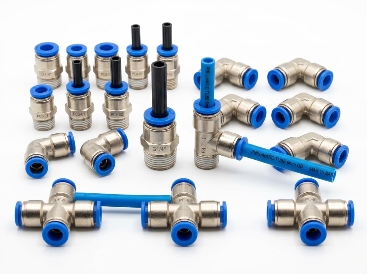
PneuPart tube fittings
Connect tubing to a valve or actuator. Match tube outside diameter, port thread and seal type.
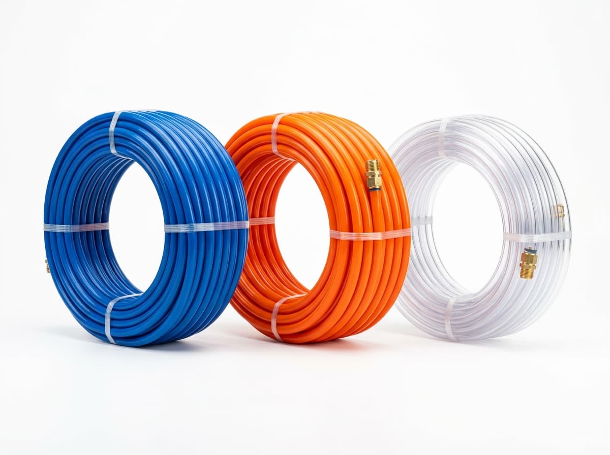
Product-group reference image
PneuPart pneumatic tubing
Run air lines between fittings and components. Confirm outside diameter, bend radius, pressure and temperature.
Planning a Complete Circuit or Multi-Item BOM?
Send your parts list, connection sizes and operating conditions for a matching check and combined quotation.