Find your SCF type
Choose a type; send a model or photo if unsure.
SCF
Valve-equipped single-rod cylinder
Send the model, quantity and destination. For multiple items, attach a parts list or BOM.

SCF combines an SC tie-rod cylinder with a mounted 4M210/4M310 valve. Match bore, stroke,...
Official reference
Based on manufacturer documentation
Model support
For model confirmation
Parts lists
Code, photo, or BOM
Availability / lead time
By model and quantity
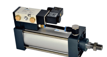
SCF combines an SC tie-rod cylinder with a mounted 4M210/4M310 valve. Match bore, stroke, mounting, valve port, coil voltage and wiring; send quantity and destination for an assembly quotation.
Know your model? Send it with the quantity for a quote. Not sure? Start with a photo, label or description. We help identify the model and clarify availability and lead time. Mixed parts lists are welcome too.
Choose a type; send a model or photo if unsure.
SCF
Valve-equipped single-rod cylinder
Send the model, quantity and destination. For multiple items, attach a parts list or BOM.
Match an SCF Cylinder and Valve Assembly
AirTAC SCF scf cylinder valve specification official Chinese reference
Helpful for Model Matching:
| Identity / supply scope | SCF is an SC single-rod double-acting tie-rod cylinder with a mounted solenoid valve, for one-to-one control. It is not SCLF front-cover locking, SCT multi-position, a locking/safety actuator, or a separate 4M valve. Request the complete cylinder-plus-valve assembly or explicitly identify replacement parts. |
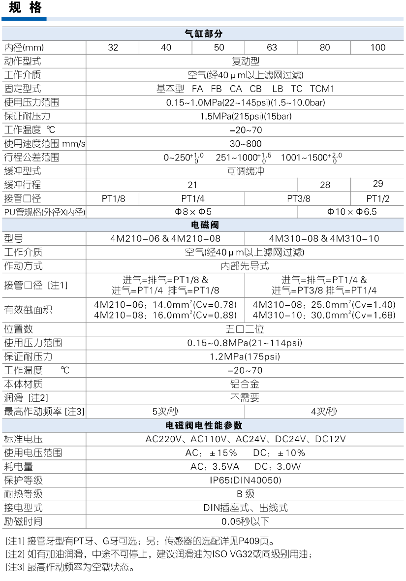
| Cylinder versus valve pressure | Cylinder operating 0.15–1.0 MPa, proof 1.5 MPa; valve operating 0.15–0.8 MPa, proof 1.2 MPa. Their common published operating interval is 0.15–0.8 MPa, not cylinder-only 1.0 MPa. Proof pressure is not an operating limit. Internal-pilot valve needs minimum pressure. |
| Bore-specific standard strokes | 32 standard 50/75/80/100/125/150/160/175/200/250/300/350/400/450/500 mm; TC starts at 100. 40/50 add 600/700/800/900/1000; TC starts at 100. 63/80/100 standard starts at 75, then 80/100/125/150/160/175/200/250/300/350/400/450/500/600/700/800/900/1000; TC starts at 125. Maximum strokes 32=1000, 40/50=1200, 63/80/100=1500 and allowable column 2000 are not complete standard lists; unlisted custom strokes require consultation. |
| Valve pairing and distinct port sizes | 32/40/50 use 4M210-06 or 4M210-08, valve main port 1/8 or 1/4 and exhaust 1/8. 63/80/100 use 4M310-08 or 4M310-10, valve main port 1/4 or 3/8 and exhaust 1/4. Cylinder ports: 32=1/8, 40/50=1/4, 63/80=3/8, 100=1/2. Valve port code 06/08/10 is not the cylinder port. Thread blank PT or G; no NPT T in SCF ordering. |
| Valve flow / pilot construction | Valve is internally piloted, five-port two-position. Effective area/Cv: 4M210-06 14.0 mm²/0.78; 4M210-08 16.0/0.89; 4M310-08 25.0/1.40; 4M310-10 30.0/1.68. These are valve flow characteristics, not cylinder speed or complete-actuator throughput. PU tube OD×ID: 32/40/50 Ø8×5mm; 63/80/100 Ø10×6.5mm. |
| Electrical ordering / connector | Voltage code A=AC220V, B=DC24V, C=AC110V, E=AC24V, F=DC12V. Blank wiring is DIN connector; I is lead wire. AC tolerance ±15%, DC ±10%; AC 3.5VA, DC 3.0W. IP65(DIN40050) and B insulation are valve electrical source ratings, not a certified protection rating for the complete installed cylinder. Excitation time ≤0.05s; maximum unloaded valve frequency 4M210=5/s, 4M310=4/s is not full-cylinder cycle rate. |
| Temperature / air / lubrication | Cylinder and valve −20 to 70°C; cylinder speed 30–800mm/s. Air filtered through 40µm or finer source condition. Valve lubrication not required; if lubricated, do not stop lubrication, source recommends ISO VG32 or equivalent. No H/N high-temperature/seal suffix published in SCF assembly ordering, even though other SC pages publish such fields. |
| Magnet / mounting / sensors | Blank no magnet or S magnetic piston. Assembly mounting basic/LB/FA/FB/CA/CB/TC; TCM1 is the TC mating accessory, not a complete-cylinder suffix. SCF accessory row: all seven mounting accessories and I/Y/U/F rod joints marked compatible; CMSG/DMSG/EMSG marked compatible only magnetic configuration. Sensor electrical/wire details referenced to printed 409 outside this PDF; confirm exact sensor and bracket before quotation. |
| Dimensions / cushion / tolerance | Own SCF drawings distinguish energised retract and energised extend layouts. Valve/tubing changes B/BA/BC/BD/CB, FA/AG and clearance; use selected bore/valve-model row, not bare SC drawing. Adjustable cushion stroke32/40/50/63=21mm, 80=28, 100=29. Stroke tolerance0–250 +1.0/0mm, 251–1000 +1.5/0, 1001–1500 +2.0/0; this does not make unlisted strokes standard. |
| Energised motion / installation | Source permits reversing valve mounting by 180° according to whether energisation retracts or extends the rod. A source warning requires alignment of the valve sealing-ring holes and adapter holes. This orientation is not a separate published assembly-order suffix. Confirm required normal/energised motion, pneumatic drawing, valve electrical label and clearance; certified fail-safe behavior is not specified. |
| Accessory codes / materials | Shared SC accessory table printed51–54 supplies F-SC[bore]LB/FA/CA/CB/TC and F-SC[bore]TCM1; FA/FB use F-SC[bore]FA source part number. Rod threads32 M10×1.25, 40 M12×1.25, 50/63 M16×1.5, 80 M20×1.5, 100 M20×1.5. Source I/Y/F/U part numbers use these thread codes; do not append them to SCF assembly code. Shared dimensional sheets depict bare SC bodies and are accessory references only; complete SCF valve clearance follows own drawings. |
Ordering code matching
Code format
SCF[bore]×[listed stroke][S][mount]-[06/08/10][A/B/C/E/F][I][G]Complete assembly; valve port and voltage requiredSCF 50 × 1000 S -06 ASCF 80 × 125 S TC -10 B I G| 1Assembly / bore / stroke | 2Magnet / mounting | 3Valve port / voltage / wiring / thread |
|---|---|---|
| SCF is an SC single-rod double-acting tie-rod cylinder with a mounted solenoid valve, for one-to-one control. It is not SCLF front-cover locking, SCT multi-position, a locking/safety actuator, or a separate 4M valve. Request the complete cylinder-plus-valve assembly or explicitly identify replacement parts. 32 standard 50/75/80/100/125/150/160/175/200/250/300/350/400/450/500 mm; TC starts at 100. 40/50 add 600/700/800/900/1000; TC starts at 100. 63/80/100 standard starts at 75, then 80/100/125/150/160/175/200/250/300/350/400/450/500/600/700/800/900/1000; TC starts at 125. Maximum strokes 32=1000, 40/50=1200, 63/80/100=1500 and allowable column 2000 are not complete standard lists; unlisted custom strokes require consultation. | Blank no magnet or S magnetic piston. Assembly mounting basic/LB/FA/FB/CA/CB/TC; TCM1 is the TC mating accessory, not a complete-cylinder suffix. SCF accessory row: all seven mounting accessories and I/Y/U/F rod joints marked compatible; CMSG/DMSG/EMSG marked compatible only magnetic configuration. Sensor electrical/wire details referenced to printed 409 outside this PDF; confirm exact sensor and bracket before quotation. | 32/40/50 use 4M210-06 or 4M210-08, valve main port 1/8 or 1/4 and exhaust 1/8. 63/80/100 use 4M310-08 or 4M310-10, valve main port 1/4 or 3/8 and exhaust 1/4. Cylinder ports: 32=1/8, 40/50=1/4, 63/80=3/8, 100=1/2. Valve port code 06/08/10 is not the cylinder port. Thread blank PT or G; no NPT T in SCF ordering. Voltage code A=AC220V, B=DC24V, C=AC110V, E=AC24V, F=DC12V. Blank wiring is DIN connector; I is lead wire. AC tolerance ±15%, DC ±10%; AC 3.5VA, DC 3.0W. IP65(DIN40050) and B insulation are valve electrical source ratings, not a certified protection rating for the complete installed cylinder. Excitation time ≤0.05s; maximum unloaded valve frequency 4M210=5/s, 4M310=4/s is not full-cylinder cycle rate. |
If the label is incomplete, send the readable parts together with a photo.
SCF 50 × 1000 S -06 A1Assembly / bore / stroke
SCF is an SC single-rod double-acting tie-rod cylinder with a mounted solenoid valve, for one-to-one control. It is not SCLF front-cover locking, SCT multi-position, a locking/safety actuator, or a separate 4M valve. Request the complete cylinder-plus-valve assembly or explicitly identify replacement parts. 32 standard 50/75/80/100/125/150/160/175/200/250/300/350/400/450/500 mm; TC starts at 100. 40/50 add 600/700/800/900/1000; TC starts at 100. 63/80/100 standard starts at 75, then 80/100/125/150/160/175/200/250/300/350/400/450/500/600/700/800/900/1000; TC starts at 125. Maximum strokes 32=1000, 40/50=1200, 63/80/100=1500 and allowable column 2000 are not complete standard lists; unlisted custom strokes require consultation.
2Magnet / mounting
Blank no magnet or S magnetic piston. Assembly mounting basic/LB/FA/FB/CA/CB/TC; TCM1 is the TC mating accessory, not a complete-cylinder suffix. SCF accessory row: all seven mounting accessories and I/Y/U/F rod joints marked compatible; CMSG/DMSG/EMSG marked compatible only magnetic configuration. Sensor electrical/wire details referenced to printed 409 outside this PDF; confirm exact sensor and bracket before quotation.
3Valve port / voltage / wiring / thread
32/40/50 use 4M210-06 or 4M210-08, valve main port 1/8 or 1/4 and exhaust 1/8. 63/80/100 use 4M310-08 or 4M310-10, valve main port 1/4 or 3/8 and exhaust 1/4. Cylinder ports: 32=1/8, 40/50=1/4, 63/80=3/8, 100=1/2. Valve port code 06/08/10 is not the cylinder port. Thread blank PT or G; no NPT T in SCF ordering. Voltage code A=AC220V, B=DC24V, C=AC110V, E=AC24V, F=DC12V. Blank wiring is DIN connector; I is lead wire. AC tolerance ±15%, DC ±10%; AC 3.5VA, DC 3.0W. IP65(DIN40050) and B insulation are valve electrical source ratings, not a certified protection rating for the complete installed cylinder. Excitation time ≤0.05s; maximum unloaded valve frequency 4M210=5/s, 4M310=4/s is not full-cylinder cycle rate.
SCF combines an SC tie-rod cylinder with a mounted 4M210/4M310 valve. Match bore, stroke, mounting, valve port, coil voltage and wiring; send quantity and destination for an assembly quotation.
SCF is an SC single-rod double-acting tie-rod cylinder with a mounted solenoid valve, for one-to-one control. It is not SCLF front-cover locking, SCT multi-position, a locking/safety actuator, or a separate 4M valve. Request the complete cylinder-plus-valve assembly or explicitly identify replacement parts.
Cylinder operating 0.15–1.0 MPa, proof 1.5 MPa; valve operating 0.15–0.8 MPa, proof 1.2 MPa. Their common published operating interval is 0.15–0.8 MPa, not cylinder-only 1.0 MPa. Proof pressure is not an operating limit. Internal-pilot valve needs minimum pressure.
SCF
SCF Add other models, quantities, photos, drawings, or a BOM. One request can cover several product groups.
Build your pneumatic circuit with complementary components. Confirm dimensions and operating conditions before selecting a combination.

Product-group reference image
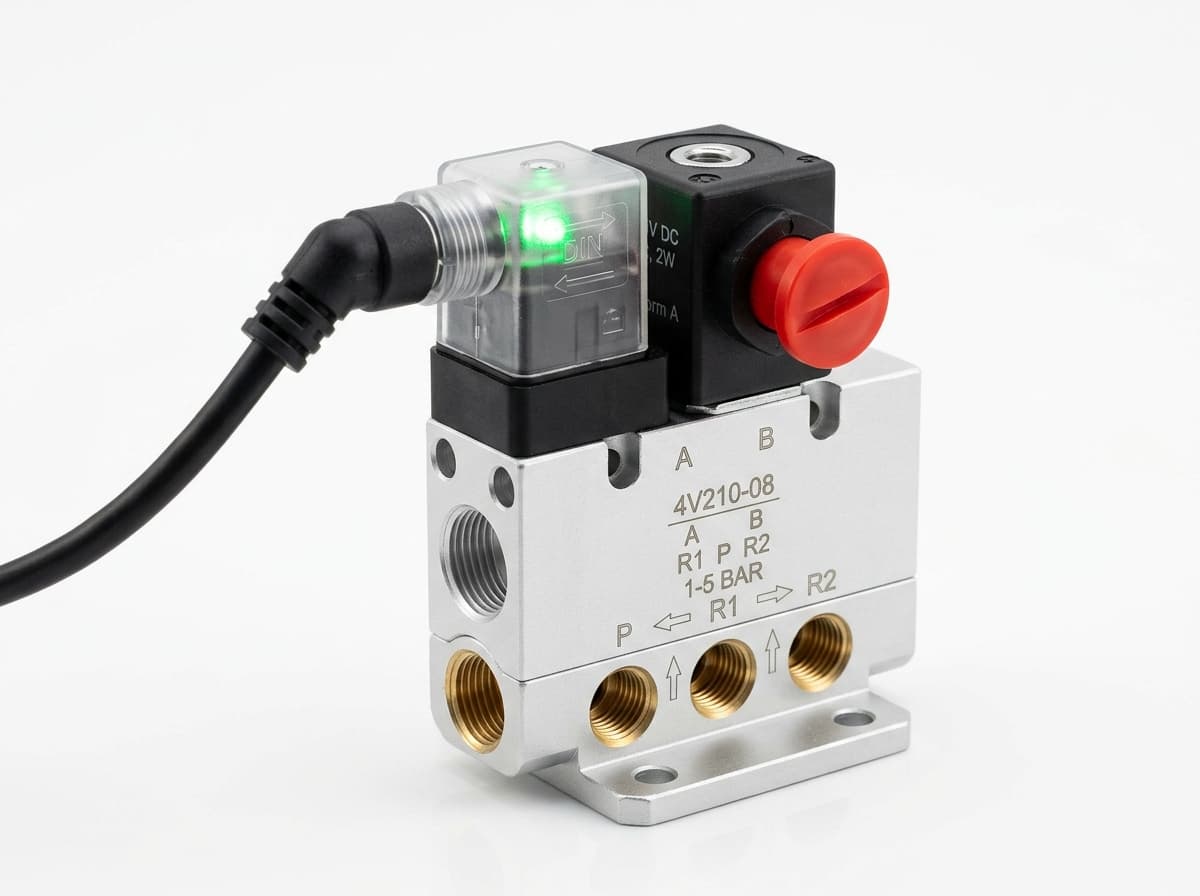
Switch the pneumatic circuit. Select the valve function, flow capacity, port size and control signal for the application.

Product-group reference image
Control actuator air flow. Confirm thread, tube size, flow direction and required flow rate.

Product-group reference image
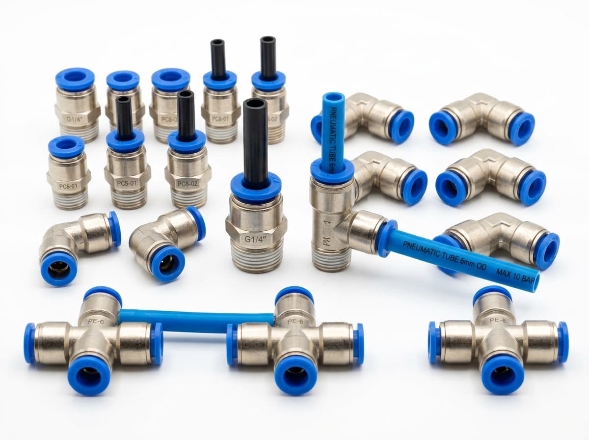
Connect tubing to a valve or actuator. Match tube outside diameter, port thread and seal type.

Product-group reference image
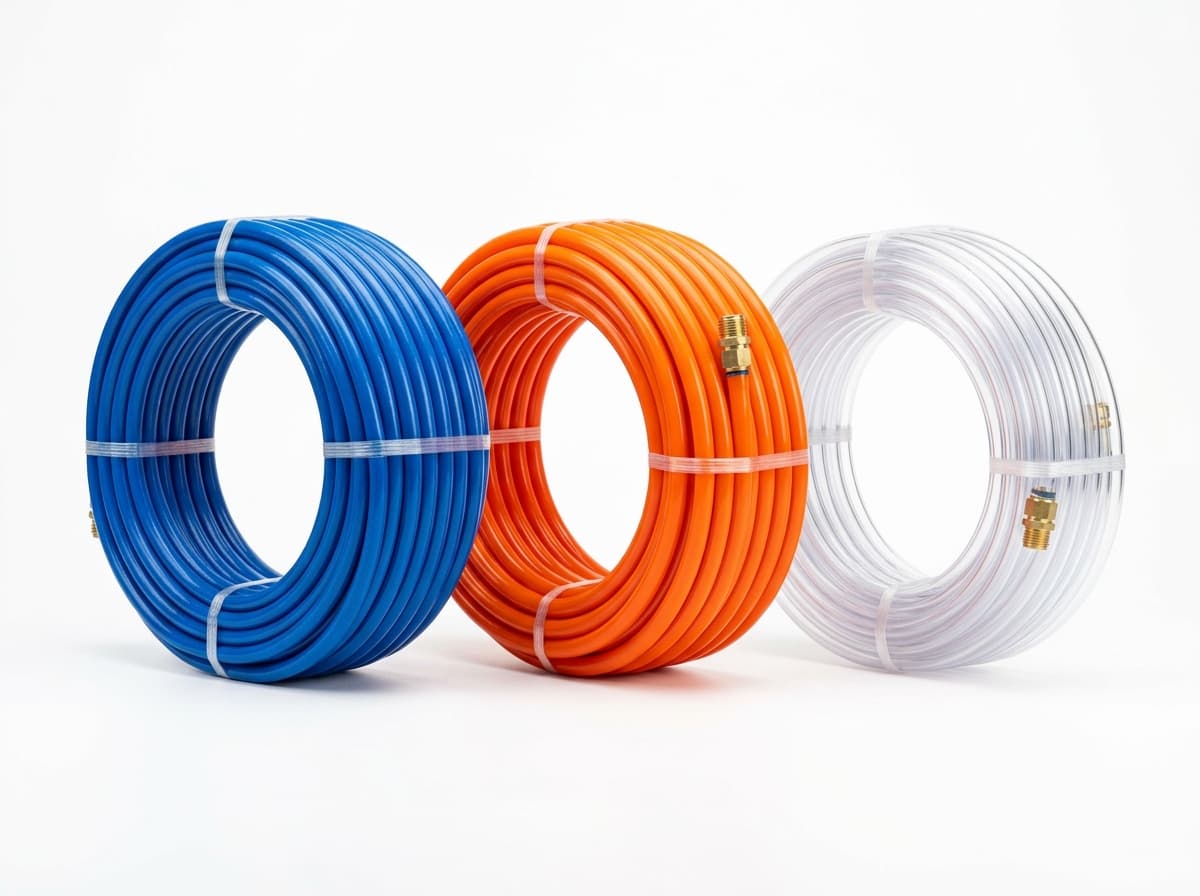
Run air lines between fittings and components. Confirm outside diameter, bend radius, pressure and temperature.
Send your parts list, connection sizes and operating conditions for a matching check and combined quotation.