Find your SCL type
Choose a type; send a model or photo if unsure.
SCLB
Rear-cover end lock
SCLF
Front-cover end lock
Send the model, quantity and destination. For multiple items, attach a parts list or BOM.
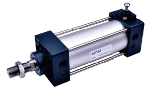
SCL end-lock cylinders support SCLB rear-cover and SCLF front-cover locking, bores 40–100 mm....
Official reference
Based on manufacturer documentation
Model support
For model confirmation
Parts lists
Code, photo, or BOM
Availability / lead time
By model and quantity
SCL end-lock cylinders support SCLB rear-cover and SCLF front-cover locking, bores 40–100 mm. Match lock side, bore-specific standard stroke, magnet, mounting and PT/G ports; send the model and release circuit for quotation. Locking requires reaching the locking-side stroke end.
Know your model? Send it with the quantity for a quote. Not sure? Start with a photo, label or description. We help identify the model and clarify availability and lead time. Mixed parts lists are welcome too.
Choose a type; send a model or photo if unsure.
SCLB
Rear-cover end lock
SCLF
Front-cover end lock
Send the model, quantity and destination. For multiple items, attach a parts list or BOM.
Match an SCL Model and End-Lock Requirement
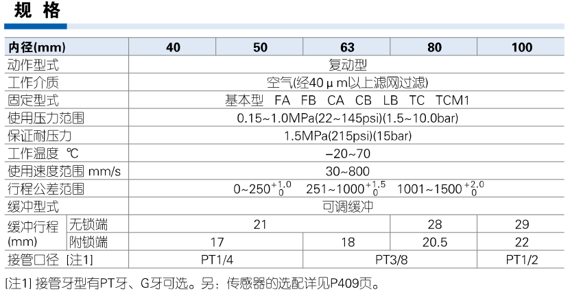
AirTAC SCL specification official Chinese reference
Helpful for Model Matching:
| Identity / lock position | SCL is an SC tie-rod double-acting cylinder with end locking. SCLB = rear-cover lock, SCLF = front-cover lock. These are not the BSC rod-clamp family. The piston must reach the locking-side stroke end; this is not arbitrary-position holding. |
| Published bores / strokes | Bores 40/50/63/80/100 mm. Bore 40 standard strokes: 25/50/75/80/100/125/150/160/175/200/250/300/350/400/450/500/600/700/800 mm. Other bores add 900/1000. Maximum columns: 40/50 = 1200, 63/80/100 = 1500; allowable column 1800 for all. These maxima do not turn unlisted strokes into standard choices. |
| Pressure / air / temperature | Operating pressure 0.15–1.0 MPa, proof 1.5 MPa; speed 30–800 mm/s. Air filtered through 40 μm; −20 to 70°C. BSC 0.7 MPa maximum and its static holding-force/unlocking-pressure values do not apply to SCL; these values are not listed in the SCL table. |
| Cylinder ports | 40/50 ports 1/4, 63/80 3/8, 100 1/2. Blank PT or G; no NPT T in ordering table. Release operates through the actual cylinder circuit; no separate G1/8 lock port is inferred from BSC. |
| Cushion end-specific | Adjustable cushion. Unlocked-side cushion: 40/50/63 = 21 mm, 80 = 28, 100 = 29. Locked-side cushion: 40 = 17, 50/63 = 18, 80 = 20.5, 100 = 22. Cushion length depends on bore and locked or unlocked side. |
| End-specific drawings | SCLB rear lock and SCLF front lock have separate product images and drawings. SCLB drawing uses A+stroke; SCLF drawing labels A+2×stroke and AB+stroke. Preserve the original drawing and confirm actual installation; do not silently replace that expression or mislabel SCLF as double rod. Magnet and non-magnet dimensions are the same. |
| Release circuit / limits | Supply the unlocking-side B port and release without load on the locking mechanism. The source advises against quick exhaust and three-position valves, especially closed-center metal-seal valves; residual pressure/leakage or lock-side back pressure can prevent locking or release it. Use the specified individual-exhaust valve arrangement and meter-out control; verify the actual circuit. |
| Maintenance / operation | Avoid excessive locked-side cushion restriction; unlock for installation/adjustment. Return manual release mechanism to its initial position and use manual operation only during adjustment. Do not drive one workpiece with two or more lock cylinders. Manual release example requires pull force >=20 N with unloaded horizontal installation or opposite-port pressurization; this is a manual-release condition, not holding capacity. |
| Unpublished capacity | This two-page source gives no static holding-force table, certified safety category or dynamic braking rating. Send load, lock position, circuit, mounting, quantity and destination for confirmation. Structure/material drawing is a specific bore example, not a universal BOM. |
Ordering code matching
Code format
SCL [B/F] [bore] × [standard stroke] [S] [mounting] [G]Lock position is mandatory; blank magnet/PT supportedSCLB50×50SSCLF63×100SFAG| 1SCLB / SCLF | 2Bore / stroke | 3Magnet / mounting | 4Thread |
|---|---|---|---|
| B rear cover; F front cover; lock side must be specified | 40/50/63/80/100; use bore-specific standard row, not max/allowable column | Blank or S; basic/LB/FA/FB/CA/CB/TC; TCM1 separate accessory | Blank PT or G, no NPT T |
If the label is incomplete, send the readable parts together with a photo.
SCLB 50 × 50 SSCLBSCLB / SCLF
B rear cover; F front cover; lock side must be specified
50×50Bore / stroke
40/50/63/80/100; use bore-specific standard row, not max/allowable column
SMagnet / mounting
Blank or S; basic/LB/FA/FB/CA/CB/TC; TCM1 separate accessory
PTThread
Blank PT or G, no NPT T
SCL end-lock cylinders support SCLB rear-cover and SCLF front-cover locking, bores 40–100 mm. Match lock side, bore-specific standard stroke, magnet, mounting and PT/G ports; send the model and release circuit for quotation. Locking requires reaching the locking-side stroke end.
The source requires the piston to reach the locking-side stroke end. Match SCLB rear or SCLF front end and confirm the release circuit; use a different family inquiry for arbitrary-position requirements.
It is an allowable-column value, not the explicit standard-stroke list. Send a custom requirement and installation drawing for confirmation.
SCL
SCL Add other models, quantities, photos, drawings, or a BOM. One request can cover several product groups.
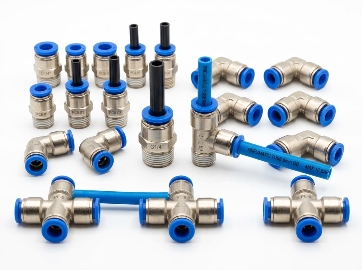
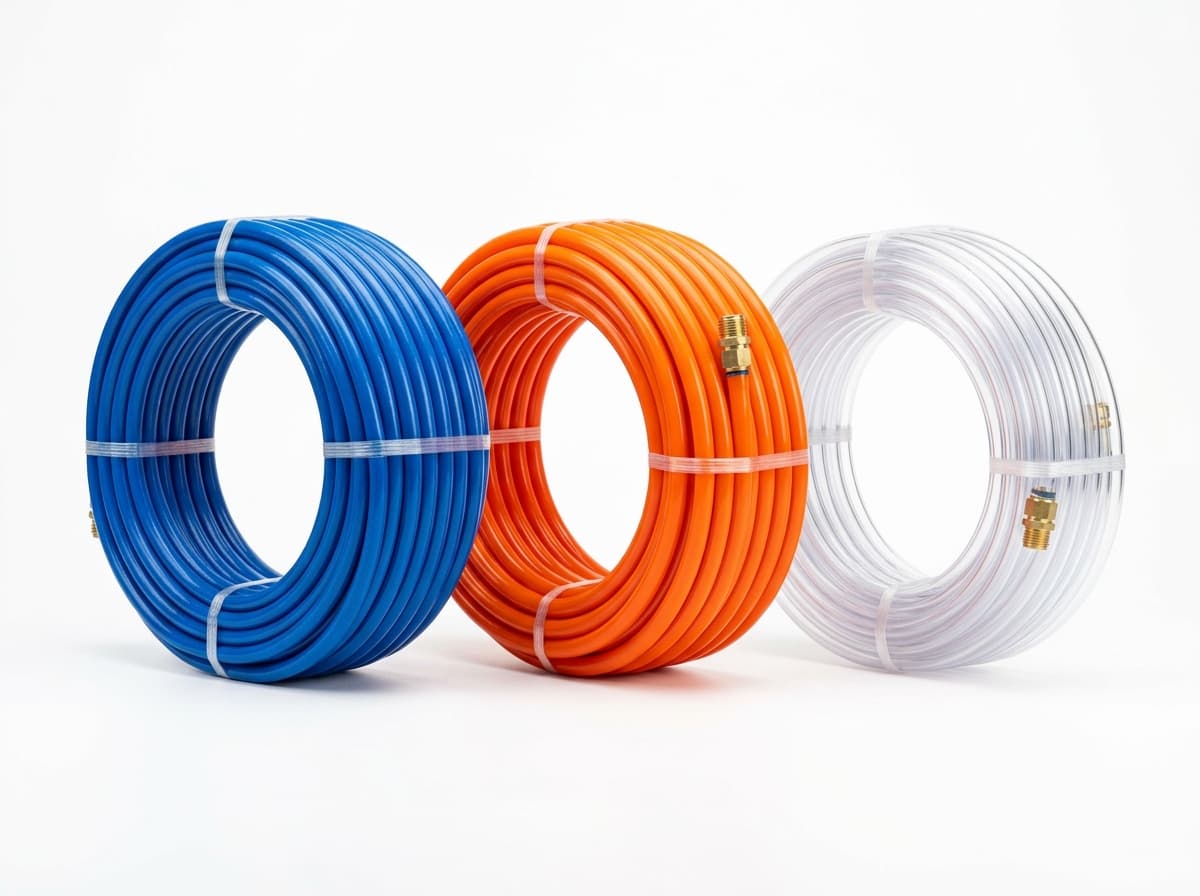
Build your pneumatic circuit with complementary components. Confirm dimensions and operating conditions before selecting a combination.

Product-group reference image
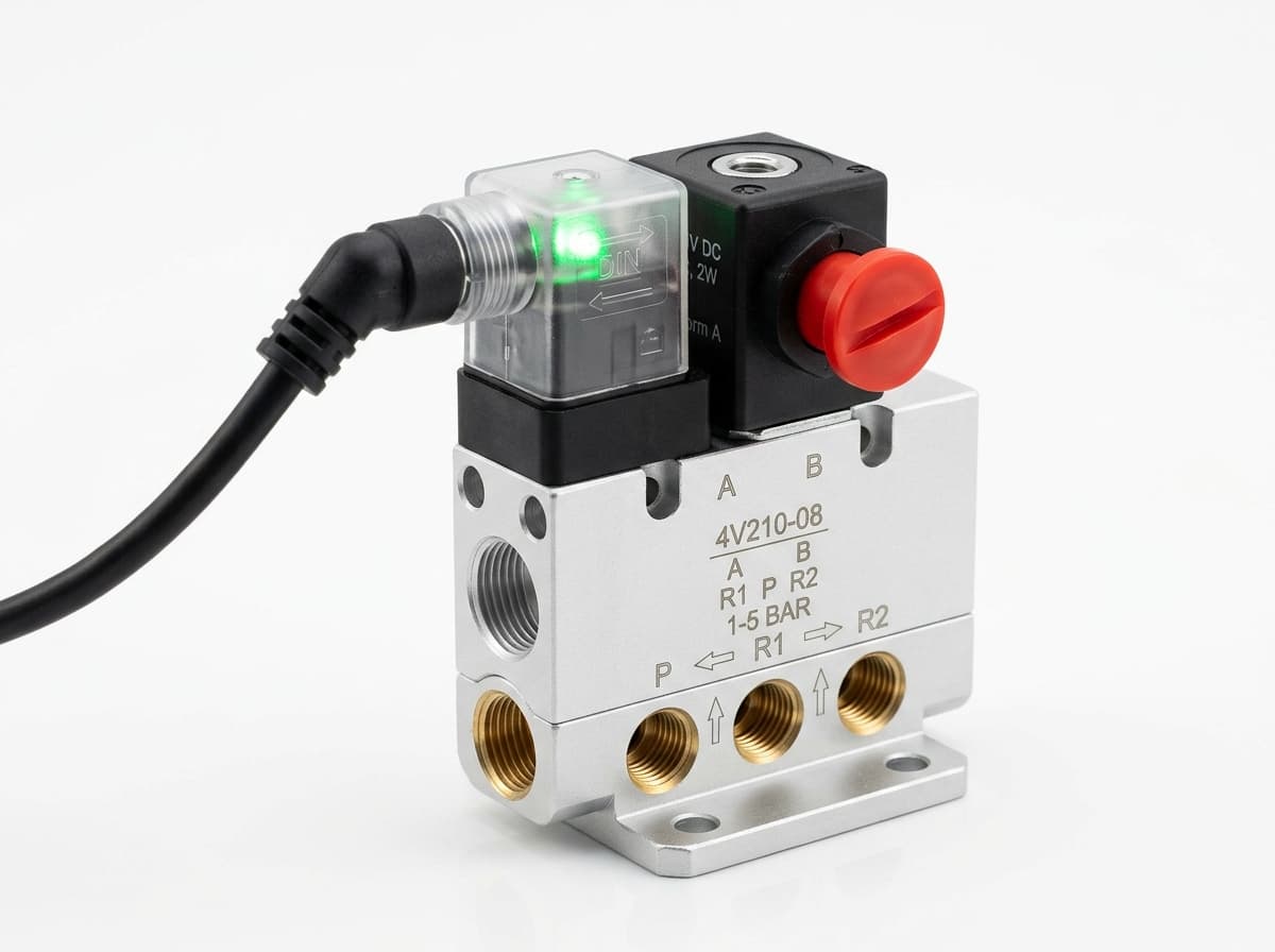
Switch the pneumatic circuit. Select the valve function, flow capacity, port size and control signal for the application.

Product-group reference image
Control actuator air flow. Confirm thread, tube size, flow direction and required flow rate.

Product-group reference image
Connect tubing to a valve or actuator. Match tube outside diameter, port thread and seal type.

Product-group reference image
Run air lines between fittings and components. Confirm outside diameter, bend radius, pressure and temperature.
Send your parts list, connection sizes and operating conditions for a matching check and combined quotation.