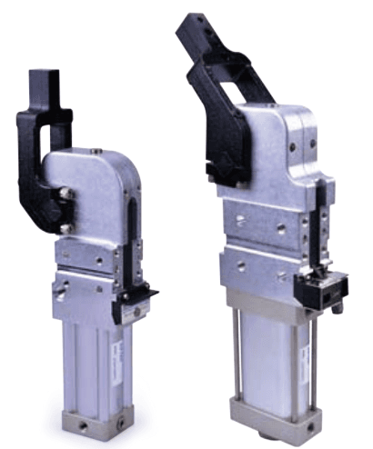
| Structure / lock | Double acting rod-crank-slider power clamp. Self-locking is reached only after the mechanism passes dead point at final clamping position and retaining pin rises. Loss-of-air closure claim applies to this state, not every arm position or a certified safety function. |
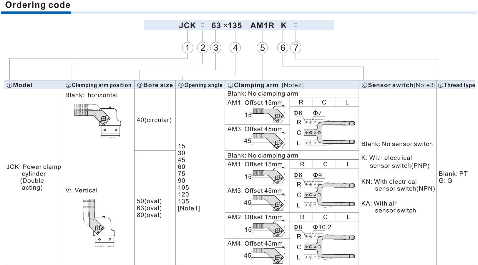
| Bore / body | Codes40/50/63/80; accessory ordering states actual bores40/50/64/80mm.40 circular; 50/63/80 oval. Keep63 code, do not rewrite64. |
| Position / arm / angle | Blank horizontal,V vertical. Angles15/30/45/60/75/90/105/120/135°.40 only AM1/AM3; AM1 horizontalmax135°,verticalmax120°; AM3max105°.50/63/80 AM1–4 horizontalmax135°,verticalmax105°.R/C/L required for supplied arms; blank no arm. |
| Arm offset | AM1/AM2 nominal15mm, except80 offset20mm. AM3/AM4 offset45mm. Arm mounting and contact geometry require the exact drawing. |
| Sensor / threads | Blank no switch; K electricalPNP; KN electricalNPN; KA air sensor only 40/50/63. BlankPT,G=G; NPT not published. Main ports40=1/8,50/63/80=1/4. |
| Operating limits | Filtered air40μm; operating0.3–0.8MPa; proof1.2MPa; −20..70°C; air buffer. Minimum1s clamping and1s opening; fit a speed-control valve. |
| Output torque / source difference | Main specification at 0.5MPa:40/50/63/80=120/160/380/800Nm. Pressure torque table gives120/165/384/803Nm. Preserve the difference and confirm actual requirement; Nm is not clamp forceN. |
| Force / lever / holder torque | Force curves depend on arm length and pressure, with maximum torque reached only at final clamping position. Maximum holder torque380/800/1500/2500Nm is not cylinder output torque or universal force. |
| Moving-arm load torque | Maximum arm-load torque for1s period:2.2/4.5/6/8Nm; 2s period:3.3/6.7/9/11.2Nm. Use arm mass and centre-of-mass offset, not fixture force as arm inertia. |
| Spacer / self-lock boundary | Spacer depth and lever length affect force; excess depth can prevent self-lock. Confirm pressing block and washer geometry. Retaining-pin manual release may spring the arm; stay outside its operating range. |
| Electrical sensor scope | DS1 KP63/KN63 applies40/50/63; KP80/KN80 applies80.10–30VDC,N.O.,PNP/NPN,rated150mAmax,30Hz,range2mm. Male connectors/cables separately specified; not assumed included. |
| Arm/screw accessories | F-JCK bore AMnR/C/L arms and F-JCK bore×angle LM adjusting screws separately orderable.40 only AM1/3; 80 noKA. Confirm accessory bore/arm/angle against cylinder before quotation. |
| Installation / adjustment | Mount standard body from4 sides; KA from3 sides. Arm pivot line,V-block order,side guide plate and washer setup follow source. Sensor/Y-knuckle gap less1.5mm. Exact angle is adjusted by screw/stroke and sensor position; SO2 end-stroke position not changeable. |