AirTAC JSCK Manual Power Clamp Cylinders
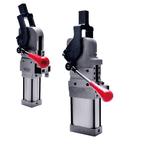
Manual JSCK power clamps with HL left or HR right handles support manual clamp/unlock as well...
Official reference
Based on manufacturer documentation
Model support
For model confirmation
Parts lists
Code, photo, or BOM
Availability / lead time
By model and quantity
Sourcing route & inquiry details
Manual JSCK power clamps with HL left or HR right handles support manual clamp/unlock as well as pneumatic operation. Select bore 40/50/63, fixed angle and arm/fixture; send sensor, quantity and destination for a quotation.
Know your model? Send it with the quantity for a quote. Not sure? Start with a photo, label or description. We help identify the model and clarify availability and lead time. Mixed parts lists are welcome too.
Match a JSCK clamp model
Part of the JSCK Series family.
View family overview →Installation Drawings & Technical Specifications
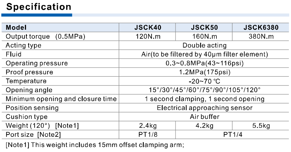
AirTAC JSCK official manual specifications
Helpful for Model Matching:
- JSCK full code or label; standard or HL/HR manual
- Horizontal/V vertical, bore and fixed opening angle
- Arm AM1–AM4 and R/C/L; intended fixture/washer setup
- Arm mass/offset, length, working pressure and clamp load
- PNP/NPN sensor, connector, PT/G and blank/B port position
- Quantity and destination
- Match standard or manual handle-specific drawing
- Check fixed angle and arm/position-specific limits
- Confirm pressure, arm mass/length, fixture washer and dead-point locking
- Separate arm kits, DIST sensor and cable/connector from clamp model
Catalogue Technical Specifications
| Pressure / medium / proof | Double acting; 0.3–0.8 MPa; 40 μm filtered air; proof 1.2 MPa; −20–70°C; air buffering; minimum 1 second clamp and 1 second open |
| Published output torque at 0.5MPa | Standard specification40/50/63/80=120/160/380/800 N·m; manual 40/50/63=120/160/380 N·m. Selection table at 0.5MPa gives120/165/400/804 N·m; confirm operating point instead of treating these as guaranteed clamp force |
| Maximum holder torque | 40/50/63/80=380/800/1500/2500 N·m at final clamping position; distinct from output torque and arm bolt tightening torque |
| Arm load torque, 1s /2s period | 40=2.2/3.3; 50=4.5/6.7; 63=6.0/9.0; 80=8.0/11.2 N·m. Check arm weight and center-of-mass offset against source curves |
| Standard angle limits | 40 horizontal AM1≤135, AM3≤105; vertical AM1≤120, AM3≤105.50/63/80 horizontal all arms≤135; vertical≤105. No-arm angles above 105 require fixture confirmation |
| Manual angle limits | 40 horizontal/vertical AM1/AM3≤105 per ordering table.50/63 horizontal AM1–AM4≤120; vertical≤105. No80 manual.40 drawing arcs conflict with ordering table; higher angles require confirmation |
| Port / arm offsets | 40 PT/G1/8; 50/63/80 PT/G1/4. AM1/AM2 offset 15mm except80 offset 20mm; AM3/AM4 offset 45mm. Arms have R/C/L position-specific hole patterns |
| Sensor / connector | K PNP, KN NPN. DIST-P/N63 for 40/50/63; DIST-P/N80 for 80.10–30V DC, N.O., rated150mA max, IP64, 2mm sensing range. Cable/connector separately selected |
| Arm bolt tightening torque | 40/50:M6×1.0, 13.8 N·m; 63:M8×1.25, 33.0; 80:M10×1.5, 66.0. Not holder or clamp torque |
| Self-lock / fixture | Self-lock occurs only after crank-slider passes dead point at final closure; washer thickness beyond final torque position can defeat locking. Standard unlock: air or retaining pin; manual also handle. Releasing pin can cause arm spring-out; keep clear of motion range |
Ordering Codes, Fit Verification & Specifications
Ordering code matching
Match each code segment
Code format
JSCK [V] [bore] × [fixed angle] [AM1–AM4 + R/C/L] [HL/HR] [K/KN] [G] [B]Manual HL/HR routes to the manual construction; accessories ordered separatelyJSCK50×120AM1RHLKGBJSCKV63×105AM4LHRKNJSCK40×105AM3CHL| 1Position | 2Bore / fixed angle | 3Clamp arm | 4Manual handle | 5Sensor | 6Thread / port position |
|---|---|---|---|---|---|
| Blank horizontal; V vertical. | Standard 40/50/63/80; manual 40/50/63. Fixed 15/30/45/60/75/90/105/120/135°, subject to arm/position/type limits. | Blank no arm; 40 only AM1/AM3; 50/63/80 AM1–AM4, each R/C/L. AM1/2 offset 15mm except80 offset 20mm; AM3/4 offset 45mm. | Blank standard; HL handle left, HR right. Manual excludes80 and has stricter angle limits. | Blank no sensor; K electrical PNP; KN electrical NPN. Separate DIST accessories and connector/cable selection. | Blank PT; G available.40 port1/8, 50/63/80 port1/4. Blank or B port position. No NPT code here. |
Quick check
Does self-lock mean any loss of air leaves the clamp safely locked?
Only the correctly set mechanism that has passed the dead point at final closure self-locks. Confirm spacer thickness, fixture and retaining-pin state; manual handles add a separate clamp/unlock method. This is not a safety certification.
JSCK-H
Include this series in a project RFQ
JSCK-H Add other models, quantities, photos, drawings, or a BOM. One request can cover several product groups.
Products to use together
Build your pneumatic circuit with complementary components. Confirm dimensions and operating conditions before selecting a combination.
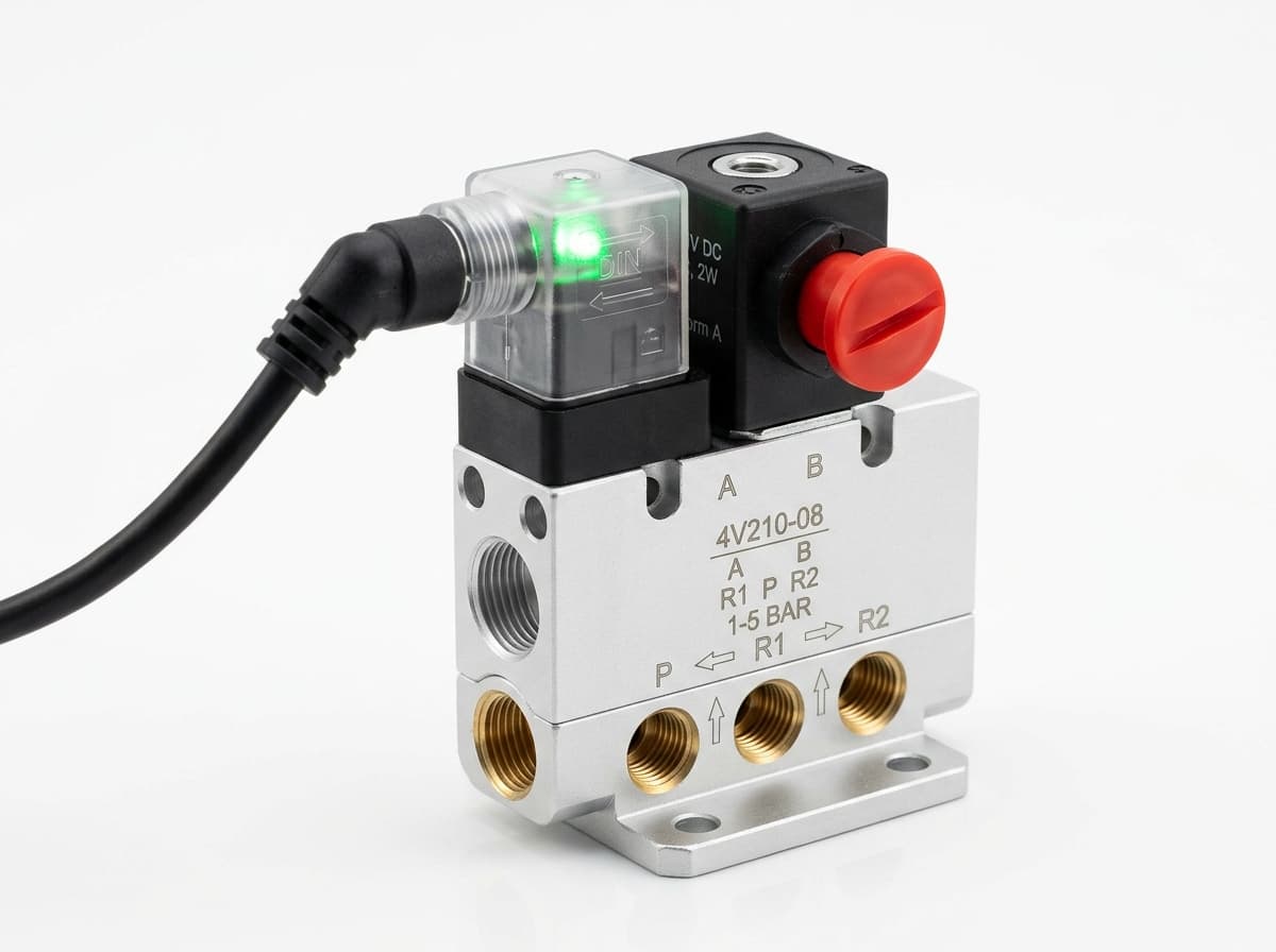
Product-group reference image
Directional control valves
Switch the pneumatic circuit. Select the valve function, flow capacity, port size and control signal for the application.
Product-group reference image
PneuPart SL speed controllers
Control actuator air flow. Confirm thread, tube size, flow direction and required flow rate.
Product-group reference image
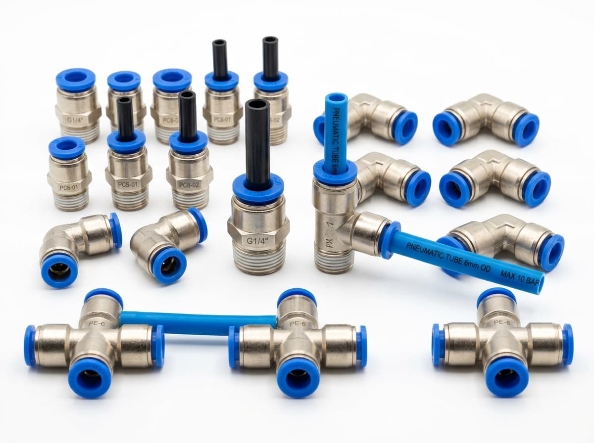
PneuPart tube fittings
Connect tubing to a valve or actuator. Match tube outside diameter, port thread and seal type.
Product-group reference image
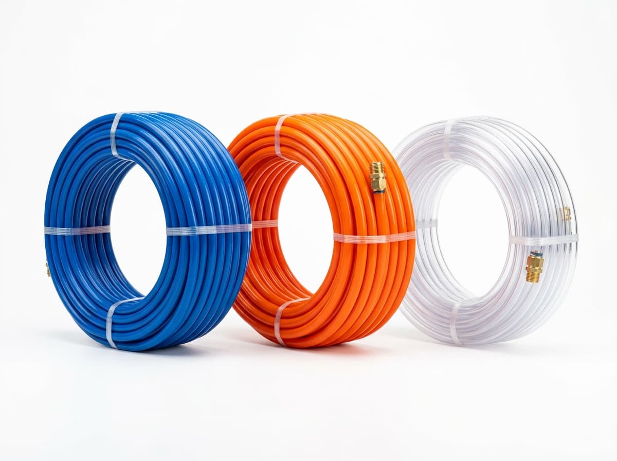
PneuPart pneumatic tubing
Run air lines between fittings and components. Confirm outside diameter, bend radius, pressure and temperature.
Planning a Complete Circuit or Multi-Item BOM?
Send your parts list, connection sizes and operating conditions for a matching check and combined quotation.