Find your MCK type
Choose a type; send a model or photo if unsure.
MCKA / MCKB
Bore 40/50/63 · two hinge widths
MCK80
Bore 80 · no A/B hinge letter
Send the model, quantity and destination. For multiple items, attach a parts list or BOM.

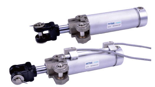
MCKA/MCKB bore 40/50/63 and MCK80, with standard strokes, optional S magnet and Y/YW knuckle....
Official reference
Based on manufacturer documentation
Model support
For model confirmation
Parts lists
Code, photo, or BOM
Availability / lead time
By model and quantity
MCKA/MCKB bore 40/50/63 and MCK80, with standard strokes, optional S magnet and Y/YW knuckle. Confirm hinge, fixture force and welding sensor scope with your RFQ.
Know your model? Send it with the quantity for a quote. Not sure? Start with a photo, label or description. We help identify the model and clarify availability and lead time. Mixed parts lists are welcome too.
Choose a type; send a model or photo if unsure.
MCKA / MCKB
Bore 40/50/63 · two hinge widths
MCK80
Bore 80 · no A/B hinge letter
Send the model, quantity and destination. For multiple items, attach a parts list or BOM.
Match an MCK Model and Hinge
AirTAC MCK specification official reference
Helpful for Model Matching:
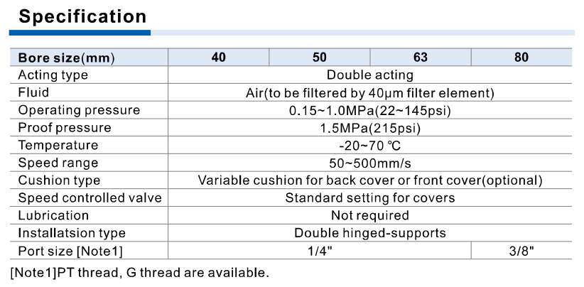
| Actuation / hinge | Double acting, double hinged supports. Bore 40/50/63 uses hinge A or B; bore 80 has no hinge letter. Cylinder drawing widths A 16.5 mm / B 19.7 mm; Y-knuckle table E is A 16.5 mm / B 19.5 mm. Confirm B mating geometry from the actual drawing. |
| Standard strokes | All bores: 50/75/100/125/150 mm. Available stroke 150 mm is not every integer below it; non-standard strokes require consultation. |
| Magnet / knuckle / thread | Blank without magnet, S normal magnet. Blank without Y knuckle; Y with M6 thread hole, YW without M6 thread hole. Blank PT, G optional; no NPT T in ordering table. |
| Pressure / proof | Operating 0.15–1.0 MPa; proof 1.5 MPa. Force table has a 0.1 MPa column, below the operating minimum: do not use that column as permission to operate at 0.1 MPa. |
| Air / temperature / speed | Air filtered through 40 μm element; −20 to 70°C; 50–500 mm/s; lubrication not required. Prevent freezing at low temperature. High-temperature requirements need a separately confirmed cylinder. |
| Ports / cushion | Bore 40/50/63: 1/4; bore 80: 3/8. Variable cushion on back cover or front cover (optional); built-in speed adjustment. Ordering table publishes blank three groups of ports and front/back cushion description, but no explicit alternate suffix. Confirm the exact cushion and piping arrangement; an alternate ordering suffix is not listed. |
| Theoretical push / pull | At 0.5 MPa, bores 40/50/63/80 theoretical push: 628/981.5/1558.5/2513 N; pull: 471/824.5/1401.5/2268.0 N. Rod diameters 20/20/20/25 mm. Cylinder axial force is not actual fixture clamping force: linkage geometry, direction and friction need confirmation. |
| Ordinary sensors | CMSG, DMSG/EMSG need separately ordered holder F-MCK40G. S is a normal magnet, not an included switch or anti-magnetic sensor package. Confirm exact switch and mounting dimensions. |
| Welding sensor / holder | Strong welding magnetic fields require anti-magnetic sensor DS1-69AM and separately ordered F-MCK40H bracket for MCK. DS1-69AM: 10–30 VDC, transistor two-wire non-polarity, normally open, max 100 mA / 3 W, 8 Hz, −10 to 70°C, IP67; AC magnetic environment rating 17000 A. Sensor temperature range differs from cylinder. Do not confuse AQK50 bracket F-AQK50H with MCK holder. |
| Sensor indication / mounting | DS1-69AM green stable range, red non-stable range; output ON spans both red and green, so red is not necessarily OFF. Common-sensor holder M5 screw tightening torque 1.2–1.3 N·m; follow exact holder diagram and avoid mechanical damage/interference. |
| HS / material boundary | Symbol row shows MCK-HS, but this catalogue ordering table defines no HS option. Preserve original HS label for manufacturer confirmation. Material illustration is based on a certain bore, not a universal component BOM. |
Ordering code matching
Code format
MCK-[A/B for 40/50/63]-bore×stroke-[S]-[Y/YW]-[G]Blank magnet/knuckle/PT options are published; HS is undefinedMCKA50×75SYGMCKB63×100SMCK80×150YW| 1Hinge / bore | 2Stroke | 3Magnet | 4Knuckle / thread |
|---|---|---|---|
| MCKA/MCKB 40/50/63; MCK 80 without A/B. | 50/75/100/125/150 mm standard; others need confirmation. | Blank without magnet; S normal magnet. | Blank no Y knuckle; Y with M6, YW without M6. Blank PT; G optional. |
If the label is incomplete, send the readable parts together with a photo.
MCKA 50 × 75 S Y GA 50Hinge / bore
MCKA/MCKB 40/50/63; MCK 80 without A/B.
75Stroke
50/75/100/125/150 mm standard; others need confirmation.
SMagnet
Blank without magnet; S normal magnet.
Y GKnuckle / thread
Blank no Y knuckle; Y with M6, YW without M6. Blank PT; G optional.
MCK is a double-acting clamp cylinder with double hinged supports, dust-scraping front seal and built-in speed adjustment. Match hinge width, bore, stroke, magnet and knuckle, then send the fixture drawing and welding environment for quotation and fit confirmation. Standard code recognition does not approve fixture force or sensor suitability.
No. S is a normal magnet. Confirm DS1-69AM and separate F-MCK40H bracket for strong welding magnetic fields; ordinary sensor holders are different.
Send the original label or requirement. HS appears in symbols but has no defined ordering option here; non-standard strokes require confirmation.
MCK
MCK Add other models, quantities, photos, drawings, or a BOM. One request can cover several product groups.
Build your pneumatic circuit with complementary components. Confirm dimensions and operating conditions before selecting a combination.

Product-group reference image
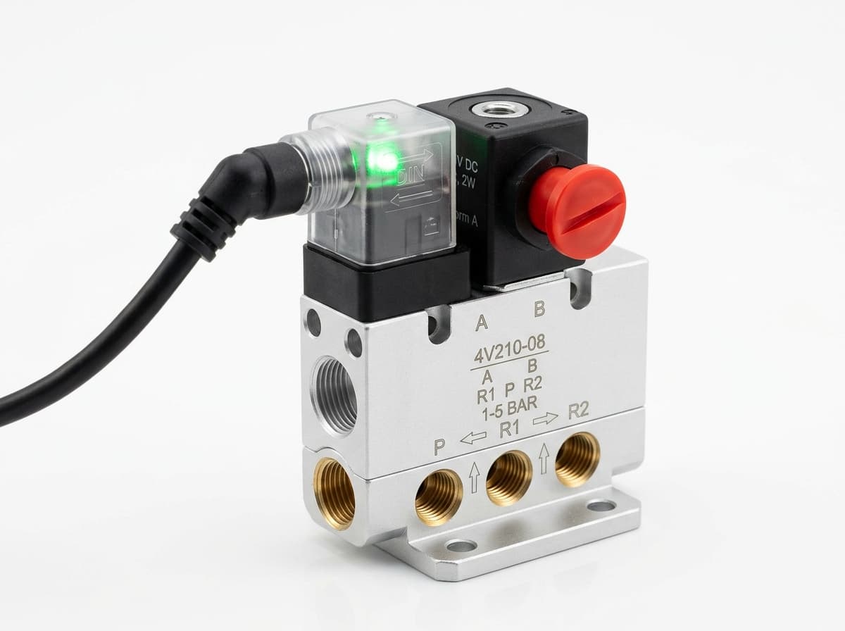
Switch the pneumatic circuit. Select the valve function, flow capacity, port size and control signal for the application.

Product-group reference image
Control actuator air flow. Confirm thread, tube size, flow direction and required flow rate.

Product-group reference image
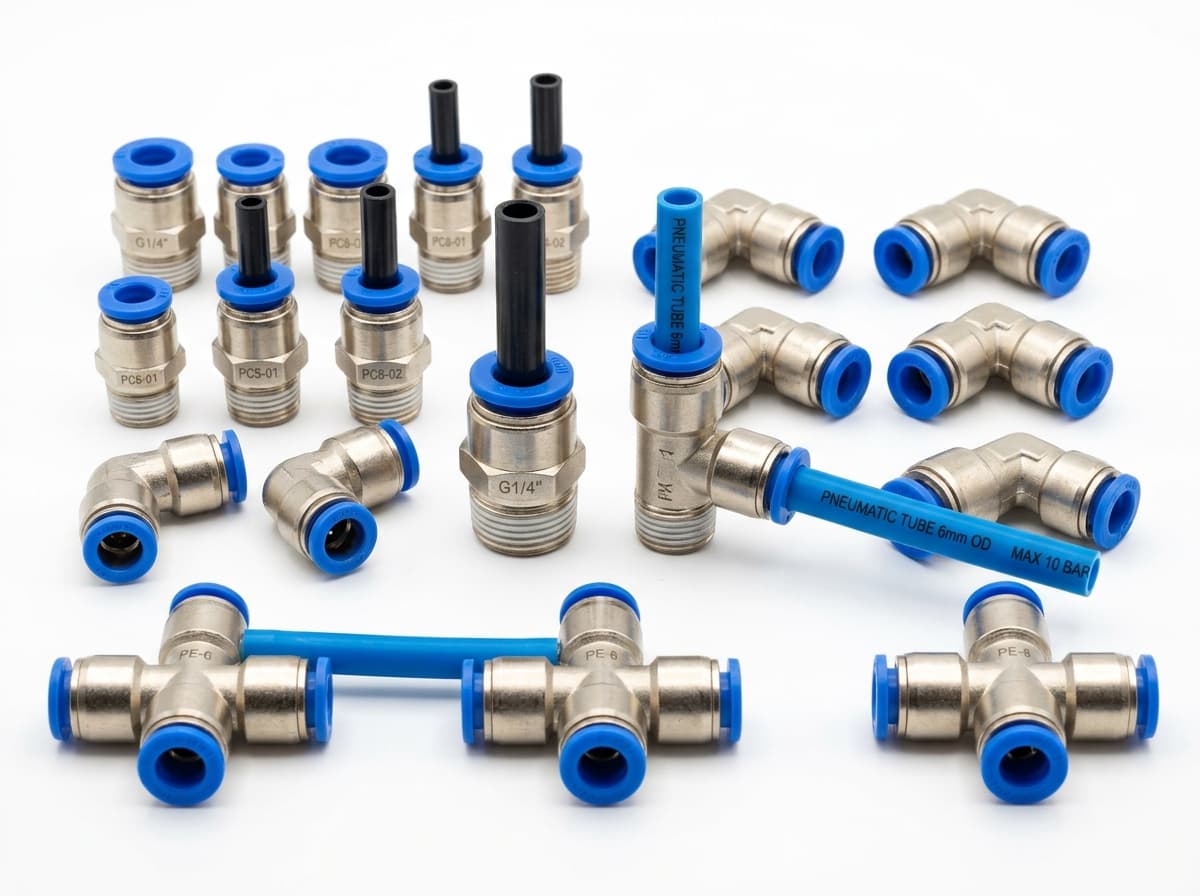
Connect tubing to a valve or actuator. Match tube outside diameter, port thread and seal type.

Product-group reference image
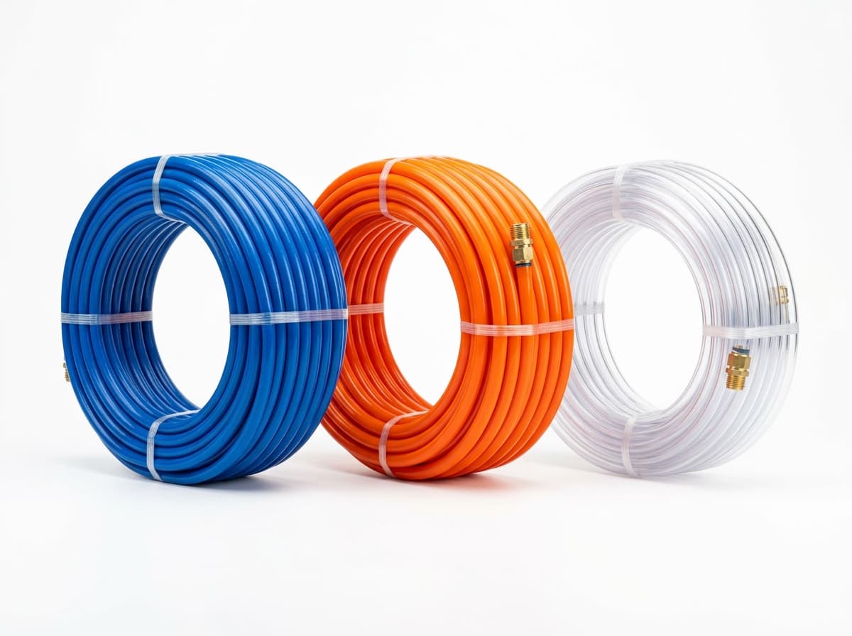
Run air lines between fittings and components. Confirm outside diameter, bend radius, pressure and temperature.
Send your parts list, connection sizes and operating conditions for a matching check and combined quotation.