AirTAC JCK KA Air-Sensing Power Clamp Cylinders
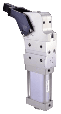
KA air-sensing structure for JCK40/50/63 with P/A/B M5×0.8 signal ports and three-side...
Official reference
Based on manufacturer documentation
Model support
For model confirmation
Parts lists
Code, photo, or BOM
Availability / lead time
By model and quantity
Sourcing route & inquiry details
KA air-sensing structure for JCK40/50/63 with P/A/B M5×0.8 signal ports and three-side mounting. Bore80 is excluded. Confirm arm/angle geometry and air-signal circuit separately.
Know your model? Send it with the quantity for a quote. Not sure? Start with a photo, label or description. We help identify the model and clarify availability and lead time. Mixed parts lists are welcome too.
Match an JCK Model and Arm Combination
Part of the JCK Series family.
View family overview →Installation Drawings & Technical Specifications
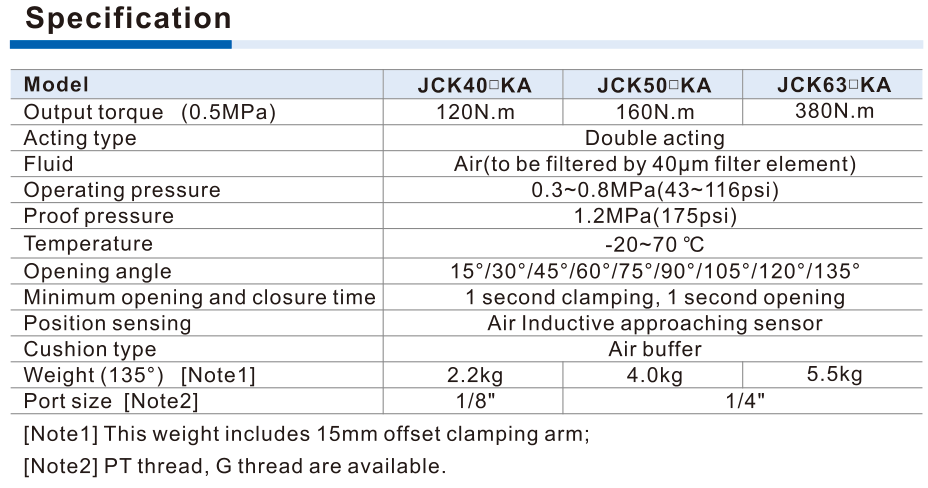
JCK KA ka specification manufacturer reference
Helpful for Model Matching:
- Complete cylinder code, horizontal/V, bore, opening angle
- ArmAM1–4 withR/C/L or no arm;arm mass, centre offset and length
- Required force, operating pressure, washer depth and final self-lock setup
- None/PNP/NPN/KA sensor, connector scope, main/signal ports
- Quantity and destination
- Match exact arm/bore and horizontal/V drawings.
- Use actual clamp length/washer depth with pressure curves.
- Confirm sensor connection and mechanical final self-lock geometry.
Catalogue Technical Specifications
| Structure / lock | Double acting rod-crank-slider power clamp. Self-locking is reached only after the mechanism passes dead point at final clamping position and retaining pin rises. Loss-of-air closure claim applies to this state, not every arm position or a certified safety function. |
| Bore / body | Codes40/50/63/80; accessory ordering states actual bores40/50/64/80mm.40 circular; 50/63/80 oval. Keep63 code, do not rewrite64. |
| Position / arm / angle | Blank horizontal,V vertical. Angles15/30/45/60/75/90/105/120/135°.40 only AM1/AM3; AM1 horizontalmax135°,verticalmax120°; AM3max105°.50/63/80 AM1–4 horizontalmax135°,verticalmax105°.R/C/L required for supplied arms; blank no arm. |
| Arm offset | AM1/AM2 nominal15mm, except80 offset20mm. AM3/AM4 offset45mm. Arm mounting and contact geometry require the exact drawing. |
| Sensor / threads | Blank no switch; K electricalPNP; KN electricalNPN; KA air sensor only 40/50/63. BlankPT,G=G; NPT not published. Main ports40=1/8,50/63/80=1/4. |
| Operating limits | Filtered air40μm; operating0.3–0.8MPa; proof1.2MPa; −20..70°C; air buffer. Minimum1s clamping and1s opening; fit a speed-control valve. |
| Output torque / source difference | Main specification at 0.5MPa:40/50/63/80=120/160/380/800Nm. Pressure torque table gives120/165/384/803Nm. Preserve the difference and confirm actual requirement; Nm is not clamp forceN. |
| Force / lever / holder torque | Force curves depend on arm length and pressure, with maximum torque reached only at final clamping position. Maximum holder torque380/800/1500/2500Nm is not cylinder output torque or universal force. |
| Moving-arm load torque | Maximum arm-load torque for1s period:2.2/4.5/6/8Nm; 2s period:3.3/6.7/9/11.2Nm. Use arm mass and centre-of-mass offset, not fixture force as arm inertia. |
| Spacer / self-lock boundary | Spacer depth and lever length affect force; excess depth can prevent self-lock. Confirm pressing block and washer geometry. Retaining-pin manual release may spring the arm; stay outside its operating range. |
| Electrical sensor scope | DS1 KP63/KN63 applies40/50/63; KP80/KN80 applies80.10–30VDC,N.O.,PNP/NPN,rated150mAmax,30Hz,range2mm. Male connectors/cables separately specified; not assumed included. |
| Arm/screw accessories | F-JCK bore AMnR/C/L arms and F-JCK bore×angle LM adjusting screws separately orderable.40 only AM1/3; 80 noKA. Confirm accessory bore/arm/angle against cylinder before quotation. |
| Installation / adjustment | Mount standard body from4 sides; KA from3 sides. Arm pivot line,V-block order,side guide plate and washer setup follow source. Sensor/Y-knuckle gap less1.5mm. Exact angle is adjusted by screw/stroke and sensor position; SO2 end-stroke position not changeable. |
| KA signal ports / circuit | P M5×0.8 signal inlet; A M5×0.8 clamping-position outlet; B M5×0.8 unclamping-position outlet. Preinstalled sealed air sensor; main cylinder ports remain1/8 for 40 and1/4 for 50/63. Confirm circuit and signal interpretation. |
Ordering Codes, Fit Verification & Specifications
Ordering code matching
Match each code segment
Code format
JCK-[blank/V]-[40/50/63/80]×[15…135]-[blank/AMnR/AMnC/AMnL]-[blank/K/KN/KA]-[blank/G]Arm-specific angle limits apply; KA excludes80; NPT not listedJCK63×135AM1RKJCKV40×120AM1CGJCK50×105AM3LKA| 1Position / arm / angle | 2Sensor / thread |
|---|---|
| Blank horizontal,V vertical. Angles15/30/45/60/75/90/105/120/135°.40 only AM1/AM3; AM1 horizontalmax135°,verticalmax120°; AM3max105°.50/63/80 AM1–4 horizontalmax135°,verticalmax105°.R/C/L required for supplied arms; blank no arm. | Blank no switch; K electricalPNP; KN electricalNPN; KA air sensor only 40/50/63. BlankPT,G=G; NPT not published. Main ports40=1/8,50/63/80=1/4. |
Quick check
Is the published torque the available clamping force?
Main specification at 0.5MPa:40/50/63/80=120/160/380/800Nm. Pressure torque table gives120/165/384/803Nm. Preserve the difference and confirm actual requirement; Nm is not clamp forceN. Force curves depend on arm length and pressure, with maximum torque reached only at final clamping position. Maximum holder torque380/800/1500/2500Nm is not cylinder output torque or universal force.
Does self-lock hold at every arm position?
Double acting rod-crank-slider power clamp. Self-locking is reached only after the mechanism passes dead point at final clamping position and retaining pin rises. Loss-of-air closure claim applies to this state, not every arm position or a certified safety function. Spacer depth and lever length affect force; excess depth can prevent self-lock. Confirm pressing block and washer geometry. Retaining-pin manual release may spring the arm; stay outside its operating range.
JCK-KA
Include this series in a project RFQ
JCK-KA Add other models, quantities, photos, drawings, or a BOM. One request can cover several product groups.
Products to use together
Build your pneumatic circuit with complementary components. Confirm dimensions and operating conditions before selecting a combination.
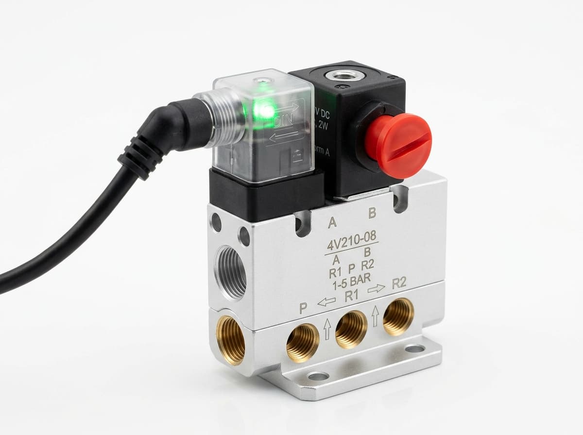
Product-group reference image
Directional control valves
Switch the pneumatic circuit. Select the valve function, flow capacity, port size and control signal for the application.
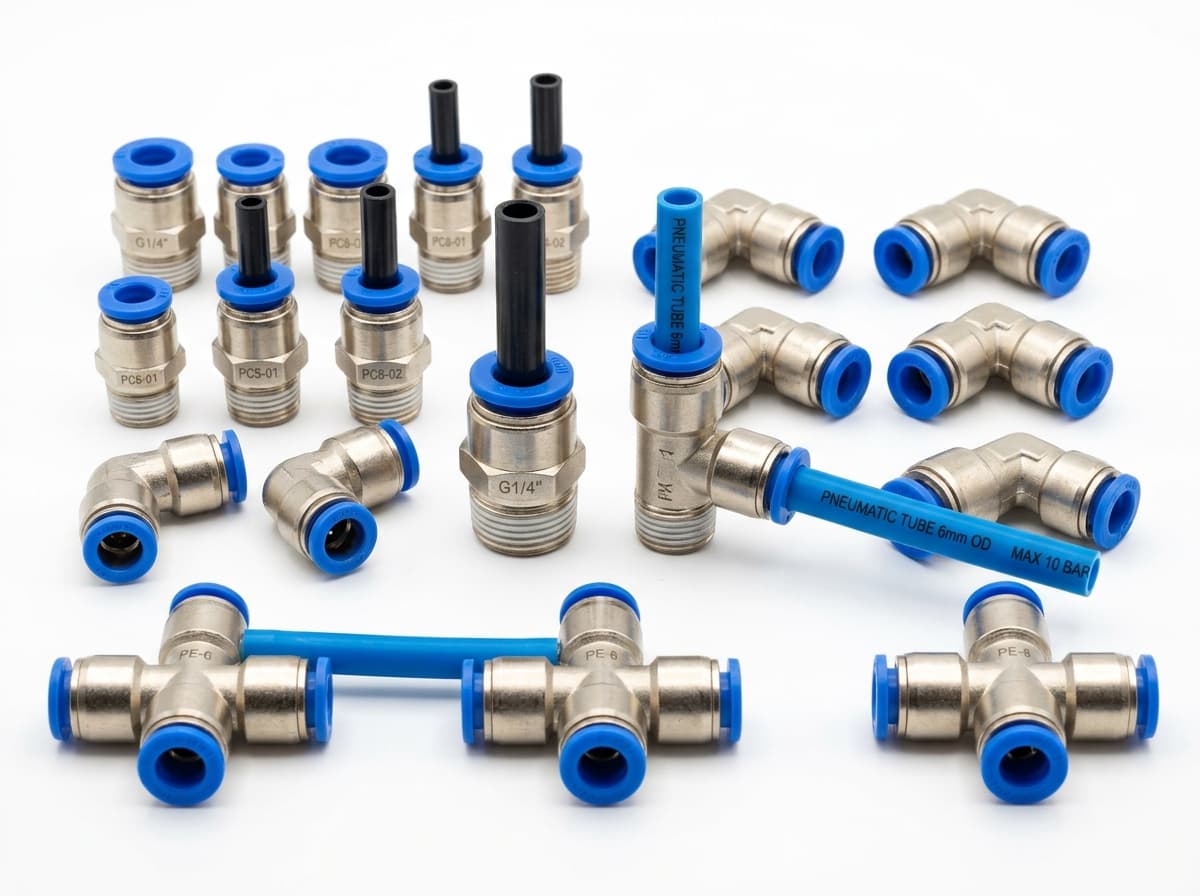
Product-group reference image
PneuPart SL speed controllers
Control actuator air flow. Confirm thread, tube size, flow direction and required flow rate.
Product-group reference image
PneuPart tube fittings
Connect tubing to a valve or actuator. Match tube outside diameter, port thread and seal type.
Product-group reference image
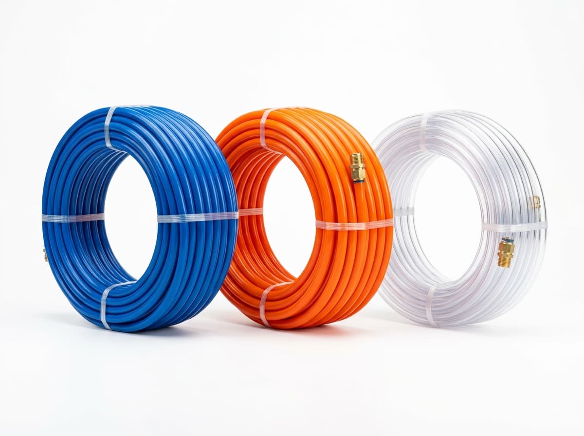
PneuPart pneumatic tubing
Run air lines between fittings and components. Confirm outside diameter, bend radius, pressure and temperature.
Planning a Complete Circuit or Multi-Item BOM?
Send your parts list, connection sizes and operating conditions for a matching check and combined quotation.